Article 250 of the National Electrical Code (NEC) focuses on grounding and bonding. This Code Article is divided into 10 separate parts — each identified by a Roman numeral. Because of the terminology and extensive Code rules (along with their many exceptions), Art. 250 is often considered difficult to understand and apply.
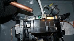
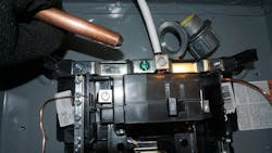
This article offers an overview of the content of each one of those 10 parts. Applying the rules for grounding and bonding requires in-depth study and familiarity by electrical workers with the rules, their exceptions, the associated tables, their notes, and the use of informational notes. Referral should always be made to Art. 100 [Definitions] ,as needed, when reading Art. 250. See the Photo for typical grounding and bonding system components.
Part I [General]
Part I details what must be accomplished through proper grounding and bonding. It is unusual for an NEC Article to provide such performance requirements. However, Sec. 250.4 does just that. The remainder of this Article tells us how to meet those requirements.
Part I provides two important visual items. Table 250.3 provides a list of an additional 37 Code Articles containing specific equipment and locations for grounding and bonding requirements found elsewhere in the NEC. Figure 250.1 (see Flowchart) provides a much-needed overview of the layout of grounding and bonding requirements. Note the grouping of the various parts into a logical format.
To help understand the performance requirements for grounded distribution systems, pay attention to the general requirements found in Sec. 250.4(A). Electrical systems are grounded for two reasons:
1) Limiting voltages imposed by lightning strikes, line surges, or unintentional contact with overhead lines, and
2) For stabilizing the voltage to earth during normal operation.
Thus, improper grounding could result in equipment damage and fire — and the voltage-to-ground would be unstable and not usable.
The 250.4 subsections on the bonding of electrical equipment and effective ground-fault current paths help you understand the purpose of bonding. Bonding joins non-current metal parts of the system together to provide a low-impedance path for current to flow from these metal components back to the source should they become energized during a ground fault. This path allows the overcurrent protective device (fuse or circuit breaker) to operate and clear the fault.
Sec. 250.8 [Connection of Grounding and Bonding Equipment] identifies seven specific methods that must be used for connecting equipment and conductors for grounding and bonding purposes. Examples include listed pressure connectors, exothermic welding, machine screws, and thread-forming screws that meet specific installation requirements. An eighth item uses a common term found throughout the Code: “other listed means.” The UL White Book is one resource to find these additional methods.
Part II [System Grounding]
This part identifies what systems are required to be grounded, systems that may be grounded but are not required to do so, and systems that must be grounded. Though this may sound confusing, it is simple to identify the applicable Code section by voltage and type system — and then apply the rules. If the electric utility provides a grounded service, which will be the general rule, then the premises’ wiring system must also be grounded. Rules for main bonding jumpers, system bonding jumpers, and grounding electrode conductors (GECs) begin to appear in Part II.
Of special interest are the grounding requirements for separately derived AC systems. The key to understanding whether systems are separately derived is to determine if the grounded conductor of the separate source remains connected to the grounded conductor of the service system grounded conductor. For example, if a standby generator supplies loads through an automatic transfer switch, is the grounded conductor switched in the transfer switch? If so, then the standby generator becomes a separate source of supply, and the rules found in this Part must be applied. This separately derived system will use a system bonding jumper anywhere between the generator and the first disconnecting means. This system bonding jumper performs the same function as a main bonding jumper at the service. However, in a separately derived system, this jumper is defined as the “system bonding jumper.” For sizing the system bonding jumper at the generator and the main bonding jumper at the service, Table 250.102(C)(1) is supplied in Part V Bonding. Using this example, it’s easy to see why the use of Art. 250 requires study and practice.
Part III [Grounding Electrode System and Grounding Electrode Conductor]
The grounding electrode system resides under the earth, and the GEC connects that system to the supply source (transformer or generator windings for example).
There are eight items permitted to perform grounding as part of the grounding electrode system, each of which has its own specific requirements, including its installation. For example, copper rods fall under rod and pipe electrodes. These rods must be at least 2.44 m (8 ft) in length and be 15.87 mm (⁵⁄₈ in.) in diameter unless listed. A subsequent section provides details on installation; rods need to be in contact with the earth for
8 ft, and they must be below the permanent moisture level (if practicable). Installation details are even provided for what must be done if rock bottom is encountered when driving the rod.
The size of the GEC is based upon the size of the ungrounded conductors (or equivalent area if parallel ungrounded conductors are installed), as shown in Table 1. Connection requirements for the grounding and bonding connections to electrodes are addressed as well as the need for bonding jumpers around insulated joints in metal piping systems.
Part IV [Enclosure, Raceway, and Service Cable Connections]
Part IV contains only three sections. These address service raceways and enclosures for grounded systems, underground service cable, and other conductor enclosures and raceways that are not part of the service.
Part V [Bonding]
Given the obvious importance of proper bonding, Part V contains 10 different sections with many subsections. Bonding services, communication systems, and bonding of systems over 250V are examples of topics. Rules for bonding piping systems and exposed structural metal are extensive. Of particular importance is Table 250.102(C)(1) for sizing grounded conductors, the main bonding jumper, the system bonding jumper, and the supply-side bonding jumper for AC systems (Table 2).
Part VI [Equipment Grounding Conductor]
The equipment grounding conductor’s (EGC’s) purpose is to provide an effective ground-fault current path (low impedance) from the non-current-carrying metal components of the system back to the source of supply and to the ground as well. As mentioned previously, this fault current path must allow for sufficient current flow such that the overcurrent protective device will operate and clear the fault. Part VI begins by identifying rules for some specific equipment. For example, Sec. 250.112 requires that motor frames, switchgear and switchboard frames, elevators and cranes, electric signs and luminaires have their metal frames connected to an EGC.
Three important sections of this part are:
- Sec. 250.118, which lists what can be used as an EGC.
- Sec. 250.119, which explains how to identify the EGC.
- Sec. 250.122, which provides a table for sizing the EGC.
Items that can be used as the EGC include copper, copper-clad aluminum, or aluminum wire type or busbar. In dwelling unit applications when using Type NMC cable, a bare copper conductor serves as the EGC. In commercial and industrial applications, a copper conductor with green insulation is typical. In addition, rigid and intermediate metal conduit, electrical metallic tubing, listed flexible and liquidtight metal conduits, and Type MC cable are common examples of different EGCs.
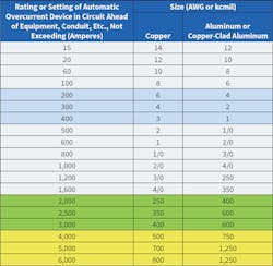
Since the purpose of the EGC is to carry the ground-fault current back to the source to allow the fuse or circuit breaker to open, the size of the EGC is based on the rating or setting of the overcurrent protective ahead of the equipment (see Table 3 as an example).
Part VII [Methods of Equipment Grounding Conductor Connections]
Part VII is the “how-to” for connecting EGCs. Since connections for separately derived systems were covered in Part II, Sec. 250.130 of this Part addresses connections made at the service equipment. For grounded systems, bonding the EGC to the grounded service conductor and the GEC is required. The main bonding jumper is used to accomplish this. In panelboard systems, this is often a green screw located in the grounded conductor busbar, which must be tightened down to make good contact with the enclosure.
Section 250.146 is an commonly used section of this Part. It requires a bonding jumper to connect the grounding terminal of a receptacle (green screw) to the metal box; with the metal box then connected to the system EGC. However, the additional subsections point out that meeting certain provisions is not required. For example, if using a metal surface-mounted box where one of the insulating washers is removed such that the yoke of the receptacle makes metal-to-metal contact with the box, a bonding jumper is not required. Other provisions exist for self-grounding type receptacles, floor boxes, and isolated ground receptacles.
Part VIII [Direct Current Systems]
Direct-current (DC) systems must comply with this part, as well as the remainder of Art. 250 that are not specifically intended for AC systems. In general, 2-wire DC systems operating at greater than 60V, but not more than 300V used to supply premises wiring systems, must be grounded. If a 3-wire DC system is supplying premises wiring, the neutral must be grounded.
The GEC for DC systems is sized differently than for AC systems. Where the AC systems utilize a table to size these conductors (Table 250.66), Sec. 250.166 provides the rules for the DC system with no table available. Just as in AC ungrounded systems, ground-fault detection is required in ungrounded DC systems. With an ungrounded system, a single ground fault will not be recognized by the upstream protective device as insufficient fault current will flow back to the source. The breaker will not trip! Should there be a ground fault on the opposite polarity conductor, a positive-to-negative fault occurs.
Part IX [Instrument Meters and Relays]
Part IX addresses the grounding and bonding requirements for current/potential transformers and relays used for protection typically found in switchgear. Secondary circuits of voltage and current instrument transformers must be grounded if the primary voltage is 300V. However, if these instrument circuits are mounted in switchgear or switchboards (as is typically the case), they must be grounded no matter the voltage.
Instrument transformers, meters, and relays operating at 1,000V or less are connected to the EGC. For these systems operating at more than 1,000V, they are not connected to the EGC but must be isolated by elevation and other means. As always, read the exception if you are applying such rules.
Part X [Grounding of Systems and Circuits of over 1,000V]
All previous rules apply if grounding systems are over 1,000V. Quite often, these systems are connected to ground through an impedance. Solidly grounded systems (no intentional resistance or impedance to ground) — unlike lower voltage systems — can be either single-point ground or multipoint grounded. Multipoint grounding involves the neutral being grounded at more than one point.
Also in this part are rules for grounding service-supplied AC systems, including impedance grounded systems. The grounding impedance must be inserted between the grounding electrode itself and the neutral point of the supply. It must be insulated for 57.7% of the phase-to-phase voltage.
Summary
Grounding and bonding continue to be one of the more difficult topics in the NEC. Remember this article is only an overview. Use Part I to understand why we ground and bond. Refer to the definitions in Art. 100. All 10 parts of Art. 250 work together to define the requirements for grounding and bonding. As proper grounding and bonding is necessary to protect people and property from the hazards of electricity, make sure you understand the rules and apply them correctly.
Randy Barnett is the electrical codes and safety program manager for NTT Training in Centennial, Colo. A certified electrical safety compliance professional (CESCP), he can be reached at [email protected].


![This graphic shows the layout of Art. 250 [Grounding and Bonding]. This Article is divided into 10 Parts. The color coding and arrows help to understand the interrelationships between parts. This graphic shows the layout of Art. 250 [Grounding and Bonding]. This Article is divided into 10 Parts. The color coding and arrows help to understand the interrelationships between parts.](https://img.ecmweb.com/files/base/ebm/ecmweb/image/2022/08/Grounding_Bonding_0822_1.62f532403bb89.png?auto=format,compress&fit=max&q=45&h=201&height=201&w=250&width=250)


