We can summarize the rules for circuit sizing and overcurrent protection of PV circuits as follows:
- Conductor ampacity before correction and adjustment. PV circuit conductors must have an ampacity of at least 125% of the calculated maximum circuit current (CMCC) [690.8(A)] before the application of conductor ampacity correction and adjustment [690.8(B)(1)].
- Conductor ampacity after correction and adjustment. Circuit conductors must have an ampacity of at least 100% of the CMCC after the application of conductor ampacity correction and adjustment [690.8(B)(2)].
- Overcurrent protection sizing. Where conductor overcurrent protection is required [690.9], size it at least 125% of the CMCC per Sec. 690.8(A) [690.9(B)].
- Conductor overcurrent protection. Size the overcurrent protection device to protect the conductor after the application of conductor ampacity correction and adjustment per Sec. 240.4.
Stand-alone systems
The alternating current (AC) output from stand-alone inverter(s) must be at least the rating of the largest single load connected to the system. Size the inverter AC output circuit conductors to the output rating of the inverter. Provide overcurrent protection per Art. 240, and locate the inverter AC output circuit overcurrent protection device at the output of the inverter [690.10].
The inverter can supply a 120V single-phase, 3-wire, 120/240V distribution panelboard, but 240V outlets or multiwire branch circuits aren’t permitted [690.10(C)]. The PV system equipment must be permanently marked with a warning label that isn’t handwritten and is of sufficient durability to withstand the environment involved [110.21(B)].
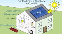
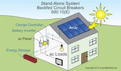
Circuit breakers that are back-fed must be secured in place by a fastener that requires other than a pull to release the breaker from the panelboard, if they’re fed from a stand-alone or multimode inverter output in a stand-alone system. Circuit breakers marked “line” and “load” aren’t suitable for backfeed or reverse current [690.10(E)] (Fig. 1).
Building supplied by PV system
A direct current (DC) disconnecting means for the PV system must open all ungrounded DC conductors [690.13]. It doesn’t need to be listed as suitable for use as service equipment [690.13(C)].
Install each DC PV system building disconnect at a readily accessible location either outside the building, or inside nearest the point of DC PV system conductor entry. Where the disconnect isn’t at the point of entry, install the DC PV conductors in a metal raceway, Type MC cable, or metal enclosure [690.31(G)].
Each DC PV system building disconnect must be permanently marked to identify it as the PV system disconnect. The disconnecting means must consist of no more than six switches or six circuit breakers mounted in a single or group of separate enclosures.
Equipment disconnects
PV equipment such as inverters, batteries, and charge controllers must have a disconnecting means that opens all ungrounded circuit conductors from all sources of power [690.15].
Where equipment is energized from more than one source, a disconnecting means is required for both the DC input and AC output. Also, they must be grouped and permanently marked and identified as to their purpose.
A single disconnecting means per Sec. 690.17 is permitted for the combined AC output of one or more inverters or AC modules in an interactive system.
Additional rules apply for:
- Utility interactive inverters installed outdoors, but not readily accessible [690.13(A)].
- DC combiners [690.15(C)].
- Fuses [690.16].
The disconnecting means for ungrounded PV DC circuit conductors must be one of the 10 listed products enumerated in Sec. 690.17. For example, a PV industrial control switch marked for use in PV systems.
Related
The PV DC disconnect must simultaneously disconnect all ungrounded conductors within the circuit. It also must be externally operable without exposing live parts and indicate whether in the open (OFF) or closed (ON) position.
Wiring methods
Wiring methods permitted for PV systems include any Chapter 3 wiring method, wiring listed for PV use, and wiring that’s part of a listed system [690.31]. Readily accessible exposed PV source or output circuit conductors operating at greater than 30V must be installed in a raceway or be guarded [690.31(A)].
PV source and output circuits can be installed in the same raceways or enclosure with each other, but not with non-PV system conductors unless separated by a partition [690.31(B)].
PV system conductors must be identified and grouped by color coding, marking, tagging, or other approved means.
Single-conductor Type USE-2 or listed PV wire can be run in exposed outdoor locations within the PV array where not readily accessible [690.31(C)(1)]. But it must be installed in a raceway when not guarded or readily accessible; see Sec. 690.31(A).
Single-conductor PV wire of any size can be installed in cable trays outdoors, if the cables are supported at intervals not exceeding 12 in. and are secured at intervals not exceeding 4½ ft [690.31(C)(2)].
Type TC-ER or USE-2 can be used outdoors for PV inverter AC output circuits for a utility-interactive inverter that isn’t readily accessible. The cable must be secured at intervals not exceeding 6 ft [690.31(D)].
Flexible cords used to connect the moving parts of tracking PV modules must be identified as hard service cords or portable power cables suitable for extra-hard usage, listed for outdoor use, water-resistant, and sunlight-resistant. In addition, they must comply with Art. 400 [690.31(E)].
Where PV DC source and output conductors are run inside a building, they must be contained in a metal raceway, Type MC cable, or a metal enclosure.
Flexible, fine-stranded conductors must terminate in terminals, lugs, devices, or connectors identified and listed for fine-stranded conductors in accordance with 110.14 [690.31(H)].
Where the sum, without consideration of polarity, of the PV system voltages of the two monopole subarrays exceeds the rating of the conductors and connected equipment, monopole subarrays must be physically separated. Also, the electrical output circuits from each monopole subarray must be installed in separate raceways until connected to the inverter. The disconnecting means and overcurrent devices for each monopole subarray output must be in separate enclosures [690.31(I).
Bipolar PV systems must be clearly marked with a permanent, legible warning notice indicating that the disconnection of the grounded conductor(s) may result in overvoltage on the equipment. But listed switchgear for bipolar systems rated for the maximum voltage between circuits with a physical barrier separating the disconnecting means for each monopole subarray can be used instead of disconnecting means in separate enclosures.
The connection to a module must be arranged so that removal of a module from a PV source circuit doesn’t interrupt a grounded conductor connection to other PV source circuits [690.31(J)].
System grounding
PV systems must comply with the following, as applicable [690.41]:
- Ungrounded systems. Circuit conductors aren’t required to be grounded to the earth, but they must comply with the requirements of Sec. 690.35.
- Grounded 2-wire system. Circuit conductors must have one conductor grounded or impedance grounded to the earth and comply with Sec. 690.5.
- Grounded 3-wire system. Bipolar PV systems must have the reference (center tap) conductor grounded or impedance grounded and comply with Sec. 690.5.
Equipment grounding (bonding)
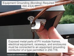
Exposed metal parts of PV module frames, electrical equipment, raceways, and enclosures must be connected to an equipment grounding conductor (EGC) of a type permitted in 250.118 [250.134] [690.43(A)] (Fig. 2). An EGC is required between a PV array and metal parts of equipment [690.43(B)].
Devices listed for grounding metallic frames of PV modules and associated equipment can be used to bond exposed metal surfaces of the modules and equipment to metal racks. Metallic mounting racks used as an EGC must have identified bonding jumpers or devices between the separate racks, and be connected to an EGC [690.43(C)].
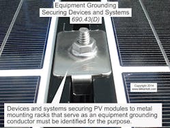
Devices and systems securing PV modules to metal mounting racks that serve as an EGC must be identified for the purpose [690.43(D)] (Fig. 3). Devices identified and listed for bonding metallic frames of PV modules can be used to bond PV modules to adjacent PV modules [690.43(E)].
There’s more. Despite being three parts, this series covered only some of the requirements for PV systems. We didn’t, for example, cover arc-fault protection [690.11], rapid shutdown [690.12], connector requirements [690.33], ungrounded systems [690.35], grounding electrode system [690.47], marking [Part VI], connection to other sources [Part VII], storage batteries [Part VIII], systems over 1,000V [Part IX], or electrical vehicle charging [Part X].
Article 690 has grown significantly over the past few Code cycles. Recent developments in solar technology, storage technology, and electrical distribution are making solar more applicable and less expensive. Expect additional requirements in future Code cycles, but carefully study the existing requirements in the meantime.
Holt is the owner of Mike Holt Enterprises, Inc. in Leesburg, Fla. He can be reached at www.mikeholt.com.


