Note: The requirements outlined in this article are based on the 2011 edition of the NEC.
Article 690, which consists of nine parts, provides electrical requirements for photovoltaic (PV) systems. Part I begins with an extensive list of definitions and includes four diagrams: 1) alternating current (AC) module system; 2) interactive system; 3) hybrid system; and 4) stand-alone system.
Although the diagrams help you identify the system components, circuits, and connections, they don’t show every detail — and are not intended for design advice. They are intended to help you understand which type of system you’re working with, so you can correctly apply the pertinent Art. 690 requirements.
Notice that the last diagram on the list is a “stand-alone system.” A PV system doesn’t always tie into a utility power system or other source. It can supply power to a building or other structure independently of an electrical production and distribution network [690.4(A)].
Other Articles of the Code also apply [690.3]. All PV installations must conform to specific requirements from Art. 90 and Chapters 1, 2, 3, and 4, except where these requirements are supplemented or modified by Art. 690. You may also need to apply requirements from Chapters 7 and 8.
Installation

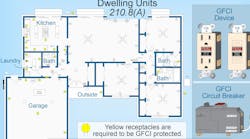
You can install conductors for direct current (DC) and AC equipment in the same raceways, outlet and junction boxes, or similar fittings with each other, but keep them independent of all other (non-PV system) wiring [690.4(B)] (Fig.1).
Identify PV system conductors by separate color coding, marking tape, tagging, or other approved means. Identification of different systems isn’t required where the identification of the conductors is evident by spacing or arrangement. The following must be identified at termination, connection, and splice points:
- PV source circuits [690.4(B)(1)].
- PV output and inverter circuits [690.4(B)(2)].
- Multiple systems. Conductor of each system where multiple systems are present [690.4(B)(3)].
Grouping. Where the conductors of more than one PV system occupy the same junction box (or raceway with removable cover), group the AC and DC conductors of each system with cable ties at least once — and at intervals of 6 ft or less. You don’t have to do this if the PV circuit enters from a cable or raceway unique to the circuit (making the grouping obvious) [690.4(B)(4)].
Module connection. Arrange module connections so the removal of a module doesn’t interrupt the grounded conductor to other PV source circuits [690.4(C)].
Equipment. Inverters, PV modules, source-circuit combiners, and charge controllers intended for use in PV power systems must be identified and listed for the application [690.4(D)].
Circuit routing. Route PV source and output conductors along building structural members (beams, rafters, trusses, and columns), where the location of those structural members can be determined by observation [690.4(E)]. If you have PV source and output conductors imbedded in built-up, laminate, or membrane roofing materials in areas not covered by PV modules and associated equipment, clearly mark their location [690.4(E)]. PV equipment, associated wiring, and interconnections must only be installed by qualified persons [690.4(F)].
Multiple inverters. Where inverters are remotely located from each other, you must install a permanent plaque (or directory) denoting all electric power sources on the premises. Install such a plaque at each service equipment location and all interconnected electric power production sources [705.10]. A directory isn’t required where all inverters and PV DC disconnecting means are grouped at the main service disconnecting means [690.4(G)].
Circuit requirements
Part II of Art. 690 starts off by requiring you to calculate the maximum PV system voltage. This equals the sum of the rated open-circuit voltage of the series-connected PV modules. Apply correction for the lowest-expected ambient temperature, per Table 690.7. For one- and two-family dwellings, the maximum PV system voltage allowed is 600V [690.7(C)].
Circuit sizing and protection

In order to properly size the circuit conductors and protection, you must first determine your maximum circuit current by making three calculations [690.8(A)]:
- PV source-circuit current. Multiply the module nameplate short-circuit current rating by 125%. This multiplier accounts for the fact that PV circuits can deliver output currents higher than their rated short circuit current for more than 3 hr near solar noon.
- PV output circuit current. Sum up the parallel PV source-circuit currents calculated in 690.8(A)(1). The PV output circuit includes the circuit conductors that run from the combiner to the inverter [690.2].
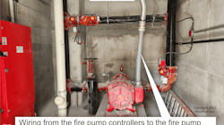
- Inverter output current. This value equals the continuous output current marked on the inverter nameplate (Fig. 2). The inverter output circuit is the circuit conductors that run from the AC output terminals of the inverter to the AC disconnect [690.2].

Next, size your overcurrent protective devices (OCPDs) [690.8(B)]. They must:
- Be sized to carry at least 125% of the maximum circuit current as calculated in 690.8(A) [690.8(B)(1)(a)] (Fig. 3).
- Comply with the terminal temperature limits in 110.14(C) [690.8(B)(1)(b)].
- Be adjusted per manufacturer’s temperature correction factors for the ampacity rating, if operating above 40°C [690.8(B)(1)(c)].
Device ratings may be sized in accordance with 240.4(B), 240.4(C), and 240.4(D) [690.8(B)(1)(d)].
Next, determine conductor ampacity. Size the PV circuit conductors to carry at least 125% of the currents as calculated in 690.8(A), before the application of conductor adjustment and correction of 310.15. Size the conductor overcurrent protection to the conductor ampacity after the application of conductor adjustment and correction of 310.15 and apply 240.4(B), 240.4(C), and 240.4(D).
The following example helps illustrate how to do these calculations. What is the minimum circuit ampacity for the inverter output circuit conductors, if the maximum continuous nameplate current rating is 24A? The conditions of use include an ambient temperature of 93°F, two current-carrying conductors in a raceway, and conductors have an insulation rating of 90°C.
Conductor ampacity = inverter nameplate current rating [690.8(A)(3)] × 1.25 = 24A × 1.25 = 30A, with a 30A OCPD
Ampacity conditions of use = 10 AWG rated 40A, Table 310.15(B)(16) at 90°C = 40A × 0.96 [310.15(B)(2)(a)] = 38.40A, permitted to be protected by a 30A OCPD.
Stand-alone systems
A stand-alone system supplies power independently of the utility [690.2]. When using a stand-alone system, the premises wiring system must meet the requirements of the Code for a similar installation connected to a service [690.10]. Additionally, wiring on the supply side of the building or structure disconnecting means must comply with the Code except:
- The AC current output from the stand-alone inverters can be less than the calculated load connected to the disconnect, but not less than the largest single utilization equipment connected to the system [690.10(A)].
- The AC circuit conductors must have overcurrent protection at the output of the inverter, sized per Art. 240 [690.10(B)].
- The inverter output can supply a 120V to single-phase, 3-wire, 120/240V distribution panel, if the panel is marked with a warning not to connect multiwire branch circuits [690.10(C)].
- Energy storage or backup power supplies aren’t required [690.10(D)].
- If a plug-in circuit breaker is backfed from field-installed conductors, then secure it by an additional fastener that can’t be released from the panelboard just by pulling on it [690.10(E)]. The purpose of the breaker fastener is to prevent the circuit breaker from being accidentally removed from the panelboard while energized, thereby exposing someone to dangerous voltage.
- Don’t backfeed circuit breakers that are marked line and load [690.10(E)].
Disconnecting means
The disconnect must open ungrounded DC circuit conductors [690.13], but you can’t use a switch, circuit breaker, or other device to open the grounded DC conductor. You don’t have to follow this restriction, if all of the following conditions are met [690.13, Exception 2]:
- The switch is used only for PV array maintenance.
- The switch is accessible only by qualified persons.
- The switch is rated for the maximum DC voltage and current, including ground-fault conditions.

The PV DC disconnect must be a manually operable switch (or circuit breaker) located where readily accessible, externally operable without exposing the operator to contact with live parts, and plainly indicating whether in the open or closed position [690.13 and 690.17] (Fig. 4).
Where all terminals of the PV DC disconnect may be energized in the open position, place a warning sign on (or adjacent to) a PV DC disconnect to indicate the hazard of energized terminals [690.14(A)].
You can place a PV source-circuit isolating switch on the PV side of the PV disconnecting means, but it’s not required [690.14(B)].
Place the DC disconnect at a readily accessible location. If you put the disconnect inside a building or structure, place it nearest the point of entrance of the PV system conductors [690.14(C)(1)].
Exception: If the PV system conductors are in metal raceway, Type MC cable, or metal enclosure inside a building or structure, you can locate the PV system disconnect remote from the structure’s point of entry [690.14(C)(1), Exception].
The PV system DC disconnect must be identified as such, and it must be suitable for the prevailing environmental conditions [690.14(C)(2)].
Utility-interactive inverters can be mounted on roofs or exterior areas that aren’t readily accessible if:
- The PV system DC disconnect is within sight of or in the inverter [690.14(D)(1)].
- The inverter AC disconnect is within sight of the inverter [690.14(D)(2).
- You install an additional AC disconnect at a readily accessible location [690.14(D)(3)].
- A permanent plaque identifies the location of the service and inverter AC disconnect if not at the same location [690.14(D)(4) and 705.10].
An interactive system is a solar PV system that operates in parallel with, and may deliver power to, an electrical production and distribution network. This is commonly called a grid-tied system.
Article 690 matches specific PV system components to requirements commonly associated with electrical sources, such as services and separately derived systems. But make no mistake, a PV system doesn’t fit either of these definitions. A PV system can be dangerous to those who are not qualified to work on them, because it is a source of electrical power that is often energized in places that a conventional electrical service would not be. Article 690 provides the requirements specific to PV systems, which must be followed carefully. We will continue this topic in Part 2, as we expand on this discussion and focus on grounding, wiring methods, and other related topics.