I’ve been a pro-sound engineer for 40+ years and a musician for 50+ years. During that time, I’ve witnessed hundreds of shock events on performance stages, recording studios, and even factory floors. A survey we ran last year on ProSoundWeb.com revealed 70% of the 3,000 musicians who responded had been shocked at least once on stage — some so severely that they were knocked unconscious. I’ve also witnessed dozens of ground-fault current events where signal cables interconnecting sound gear plugged into different electrical outlets mysteriously arced, sometimes turning red hot and melting before my eyes.
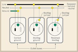
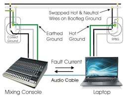
The cause behind most of these guitar-to-microphone shocks appears to be incorrectly wired electrical outlet grounds or damaged extension cords. But while a broken-off ground pin on a power cord is the obvious culprit in most home or stage shock situations, many power outlets show they’re wired correctly when checked with a 3-light outlet tester or even a voltmeter reading between H-N, H-G, and N-G, yet still present a shock hazard. Standard outlet testing methods fail to reveal one of the most dangerous miswiring situations possible, which I refer to as the “reverse polarity bootleg ground” (RPBG), as seen in the Figure.
As the illustration shows, a bootleg ground (or false ground) occurs when an ungrounded electrical outlet in an older building or stage has been improperly upgraded to a modern NEMA 5-15 or 5-20 grounded outlet. Because office building, sound stage, and home wiring installed before 1965 didn’t require a safety ground, there’s no easy way to install a grounded NEMA 5-15 outlet. Per Sec. 250.130(C) of the 2011 NEC, in that situation, a GFCI outlet should be installed with the ground wire unattached.
Under what condition can a 2-wire receptacle be replaced with a 3-wire receptacle when no ground is available in the box? Where no equipment bonding means exists in the outlet box, nongrounding-type receptacles can be replaced with [406.3(D)(3)]:
• Another nongrounding-type receptacle.
• A GFCI grounding-type receptacle marked “No Equipment Ground.”
• A grounding-type receptacle, if GFCI protected and marked “GFCI Protected” and “No Equipment Ground.”
Note: GFCI protection functions properly on a 2-wire circuit without an equipment grounding (bonding) conductor because the equipment grounding (bonding) conductor serves no role in the operation of the GFCI-protection device.
CAUTION: Permission to replace nongrounding-type receptacles with GFCI-protected grounding-type receptacles doesn’t apply to new receptacle outlets that extend from an existing ungrounded outlet box. Once you add a receptacle outlet (branch circuit extension), the receptacle must be of the grounding (bonding) type and must have its grounding terminal grounded (bonded) to an effective ground-fault current path in accordance with 250.130(C). However, the Code states this outlet must be clearly marked on front as being ungrounded. Because GFCI breakers don’t need a ground wire to function properly, this type of outlet isn’t a shock hazard. Even if the chassis of an appliance becomes electrically energized due to a high-pot failure, for example, anyone touching the appliance and ground simultaneously would exceed the 4mA to 6mA GFCI trip threshold and be protected from electrocution.
Some electricians and DIYers take shortcuts when replacing receptacles in older residences and stages by installing a grounded NEMA 5-15 outlet and strapping the ground screw to the neutral screw on back of the outlet, creating a classic bootleg ground situation. Although this practice is a Code violation, it occurs more often than you think. And because many electrical inspectors rely on a simple 3-light “cube” tester to verify correct wiring connections at outlets, any RPBG outlets can go undetected.
Testing with a 3-light tester
An RPBG outlet will test as correctly wired using any 3-light tester (Photo 1), because there’s no reference to actual earth potential. What makes an RPBG outlet so dangerous is that any appliance (refrigerator), sound gear (guitar amplifier), or even an RV or boat plugged into an RPBG appears to operate normally. But the chassis of the “grounded” appliance is now directly connected to the “hot” wire in the outlet with a low-impedance current path, and anyone touching the body of the appliance will be electrically biased to a full 120V. That situation itself is not dangerous due to the “pigeon on the power line effect.” But if a person touches the door handle on the refrigerator, strings of the guitar, or metal door of the RV plugged into an RPBG outlet while also touching anything that’s correctly earth grounded, they will receive a potentially deadly shock (around 100mA of current at 120V). Just 10mA of current through your body will result in a painful shock, and 100mA of current for a few seconds is probably lethal if not immediately treated by a defibrillator.
Note that these potential shock currents flow through the ground contact of the outlet, and avoid the neutral and hot contact current paths. So any GFCI outlet wired on a branch circuit extension downstream of an RPBG outlet will probably not sense unbalanced H-N currents and thus won’t trip as designed. In fact, because the GFCI can’t disconnect its own ground contact from the now electrified ground wire, even if it trips, there will still be the full branch current available for the ground fault path up to the circuit breaker trip current (typically more than 20A).
Testing with a voltmeter
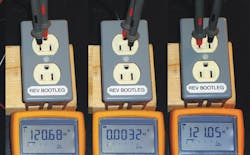
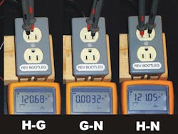
Don’t think a voltmeter is any smarter than a 3-light cube tester. If you simply measure from H-G, G-N, and H-N using any analog or digital voltmeter, you’ll find an RPBG outlet will appear normal (Photo 2). The only hint there’s a bootleg ground is that the G-N reading will be very close to 0V, while in a loaded branch circuit with correctly isolated G-N outlets, you’ll likely see at least 1/2 to a few volts difference between ground and neutral due to voltage drops in the neutral bus.
Testing with an impedance tester
Now that we know a 3-light tester and a voltmeter can’t identify RPBG outlets, what other device can we try? A ground loop impedance tester, perhaps? Although it can properly identify a bootleg ground due to the G-N impedance being too low, it cannot identify an RPBG either. See my proof of concept video at http://tinyurl.com/kpbusuw.
In Photo 3, the ground impedance tester is indicating a (F)alse bootleg ground, but the device can’t tell if the outlet has correct polarity or reverse polarity. It only indicates the false ground with a flashing (F) because the ground-to-neutral impedance is too low. But if an RPBG outlet is feeding an extension outlet on that same branch circuit, the extra resistance of the added wire length would fool the ground impedance tester, indicating 100% Code compliance. Even a visual inspection of a “properly wired” extension outlet fed from an RPGB outlet probably wouldn’t turn up any obvious problems. Note that its neutral and ground connections are both at 120V with respect to earth potential.
A testing solution that works
The gold standard method to identify this sort of miswired outlet device is to use a voltmeter connected to a known good earth ground to test each hot, neutral, and ground conductor in all outlets. But in reality, this type of test isn’t done except perhaps as part of a post-accident forensics investigation.
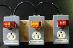
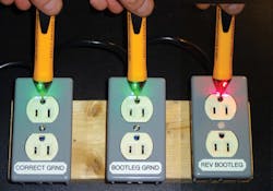
However, a simple test you can use is to check the outlet with a mid-voltage non-contact capacitive voltage tester (90V to 1,000V range), commonly referred to as an non-contact voltage tester (NCVT) When this tester is used on a properly wired outlet, you’ll hear a beep or see a light only when its tip is inserted in the “hot slot” of an outlet. However, when this type of tester gets anywhere near the front or ground contact of an RPBG miswired outlet, it typically beeps/lights from inches away, because the internal ground strap in the outlet will be biased to 120V, which provides a large electrified surface area (Photo 4). The green light on the left and center outlets indicates no or low-voltage (under 40V), while the red light on the right outlet indicates a hot ground condition (typically more than 40V for most standard sensitivity NCVTs). Although using a DMM to test between a known earth ground to each outlet contact is the gold standard, adding this NCVT check for RPBG outlets to your test procedure could save lives and dollars.
Sokol is lead instructor of the No~Shock~Zone seminars and writer for www.NoShockZone.org. He can be reached at [email protected].
SIDEBAR 1: Interconnected Outlet Fault Currents
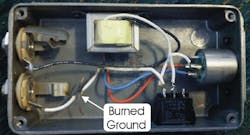
While the shock hazard created by a reverse polarity bootleg ground (RPBG) outlet is bad enough, if multiple appliances or gear are plugged into separate electrical outlets — one of which is wired incorrectly as a RPBG — then any signal or control cable between the appliances will be subject to short circuit fault currents between the correctly wired outlet’s ground and the RPBG outlet’s ground, which is actually connected to the incoming hot wire. Because these signal cables are typically small diameter (22 gauge), they don’t offer a low enough impedance to created sufficient fault current that will trip a 15A or 20A circuit breaker. The interconnecting gear often becomes the “fuse” heating up red hot before a wire or circuit board trace melts and opens the ground fault path (Photo).
It’s important to note that this equipment failure does not remove the electrocution hazard, given the fact that a technician handling the gear will be still be touching a chassis that is directly connected to the incoming 120V line.
SIDEBAR 2: Home Studio Horror Story
By Adam Olson, Studio Prime
About 10 years ago, I moved to a house five minutes from downtown Denver and decided to turn the upstairs into a recording studio. The house was more than 100 years old with 2-prong (ungrounded) electrical outlets. I was planning on replacing these old outlets with new grounded outlets myself, but in the end, felt it was best to have a licensed electrician do the work.
The electrician I hired came in and rewired the house/studio. However, instead of running new conductors back to the service panel (difficult and expensive in a house of this age) or using GFCI outlets with floated grounds, he simply installed a bootleg ground on the ungrounded boxes using “grounded” outlets. After he tied the ground screw to the neutral wire on the new 3-prong outlets and checked them with a 3-light tester, he said everything was ready to go.
However, over the course of the next month or so, a series of strange events began to occur. The first event happened after I purchased a refurbished computer printer for a couple hundred dollars. The printer was placed in the kitchen and used the same electrical outlet as the refrigerator. I connected a long USB cable from the studio computer to the printer just out of convenience. However, when I plugged in the USB cable, I saw sparks where it plugged into the printer. Assuming there was something wrong with the printer, I returned it to the store for a warranty replacement.
A few weeks later a computer audio interface died after connecting it to a laptop computer. Because this particular model had a history of Firewire failures, it was fixed under warranty. Again, I assumed the Digi box was a problem rather than the electrical outlet, since everything else seemed to be working correctly.
Weeks passed, and other similar mysterious events happened as I interconnected signal wires between various pieces of audio gear (Figure). But the big incident that sent me into full-scale investigation occurred when I connected an audio cable from my new laptop to my audio mixing console, which was powered by a different wall outlet. Once again, sparks flew, and smoke poured out of my new $2,000 laptop!
I used a DMM on each of the outlets, and they tested as expected. Clearly, there was an issue between the outlets. So I ran an extension cord and checked the voltages between the outlets. The results surprised me. I was reading 120V between the grounds of the two different outlets. Flabbergasted, I went and purchased a 3-light tester, which showed all outlets were wired correctly. But after reading the packaging carefully, I found that it stated that the 3-light tester wouldn’t indicate failure if both the neutral and ground contacts were “hot.”
My father is a licensed appliance repairman, and he guided me through documentation and proper steps for
reimbursement for damage. As expected, when the electrician returned, he denied that it could have been anything he did, and informed me that he had tested the outlets properly with a 3-light outlet tester. However, after he saw the tests I ran — coupled with the warning on the packaging that stated 3-light testers don’t work for this type of wiring arrangement — he wasn’t too happy. At this point, I proposed that he rewire the outlets correctly and reimburse me for the damages. His first response was that he wasn’t going to do anymore wiring in my place at all. However, after going outside to call his boss, he returned about 20 minutes later and started to work again. This time, he ran a new dedicated 20A circuit to a new outlet, drilling a hole through the wall and brick to boot!
After much paperwork and time, all reimbursements were made, and my studio was back up and running. The final cost to the electrician was more than $6,000, which included reimbursement of my wrecked and damaged sound gear and computer.
