This is the final installment of a three-part series on the importance of arc flash labeling of electrical equipment. In Part 1, which ran in the September 2011 issue, we considered the low-level task of taking measurements within a non-fused safety switch that serves as a local motor disconnect and learned that the level of arc flash risk can be significant, depending on the amperage and class of the upstream fuses in the motor starter compartment and the length of the branch circuit conductors running from the fuses to the safety switch. In Part 2, which ran in the October 2011 issue, we moved further upstream to a combination motor starter bucket of a motor control center and learned once again that the level of arc flash risk can defy expectations, depending on the instantaneous setting of the upstream solid-state trip unit and the feeder length to the motor control center.
In this final installment, we focus our attention on the main switchboard in the example system shown in Fig. 1 (click here to see Fig. 1). As we can see in the one-line diagram of Fig. 1, the 3-phase electric service of the commercial facility is fed from the electric utility at 13.2kV and transformed to 480V via a 1,500kVA, dry-type, delta-grounded wye main transformer (TX-1). The main transformer is protected on the primary side by fused switch FUPS. On the secondary side, the main switchboard SWBD0 is composed of main secondary breaker MB0 and four feeder breakers (FB1, FB2, FB3, and FB4); all are molded-case circuit breakers equipped with solid-state trip units. The feeder breakers serve a motor control center (MCC1), two lighting panelboards (LP2A and LP2B), a conveying system switchboard (SWBD3), and induction motor drive (M6). MCC1 consists of five combination motor starters with fused disconnects for induction motors M1 through M5. The main feeder for the lighting panelboards travels some distance from FB2 to a junction box JB2, and two short subfeeders travel from JB2 to the main breakers MB2A and MB2B of LP2A and LP2B, respectively. The four fused disconnects of SWBD3 feed the integral, non-fused disconnects of the conveying system control panels (CP3A, CP3B, CP3C, and CP3D).
Table 1 (click here to see Table 1) presents the results of arc flash calculations per IEEE Std. 1584 at main switchboard SWBD0. Note that the results depend on the upstream trip device that clears the arc fault. Referring to Table 1, if primary fused switch FUPS serves as the upstream trip device for an arc fault at SWBD0, the incident energy level is 104.8 cal/cm2. This extreme incident energy level exceeds the upper limit of the highest Hazard/Risk Category 4 (i.e., 40 cal/cm2), and work on the switchboard cannot proceed until it has been put in an electrically safe work condition per Article 120 of NFPA 70E. However, if the main secondary breaker (MB0) serves as the upstream trip device, then the incident energy level is much lower (5.3 cal/cm2), which corresponds to a Hazard/Risk Category of 2*.
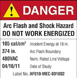
Based on Table 1, one may mistakenly believe that the extreme incident energy level applies only to the MB0 compartment of main switchboard SWBD0. However, an explosion due to an arc fault in a feeder breaker compartment could spread to all compartments of the switchboard (because the switchboard of this example is not arc resistant in construction) and render MB0 incapable of clearing the fault. Thus, the extreme incident energy level applies to all compartments of the switchboard, as shown in Table 2 (click here to see Table 2). Figure 2 provides a sample of an NFPA 70E-compliant arc flash label for the extreme incident energy level noted previously.
In conclusion, we hope that the examples of this three-part series reinforce the importance of conducting an arc flash study. This type of study will help you gather the information needed to meet the arc flash labeling requirement of Sec. 130.3(C) of NFPA 70E-2009, Standard for Electrical Safety in the Workplace.
Finally, keep in mind that an arc flash study by itself is not a substitute for electrical safety training and an ongoing electrical safety program. These types of training courses and safety procedures are still required for both in-house and contracted workers who work on or near energized electrical equipment.
Mercede, P.E., is principal of Mercede Engineering LLC, based in Bryn Mawr, Pa. He can be reached at: [email protected].
