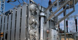
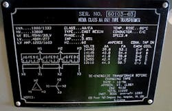
All transformers have nameplates, and all manufacturers use the same nomenclature for capacity, ratings, impedance, and other pertinent information. This article focuses on dry- or oil-type transformers, which have both ventilated self-cooled or forced-air cooling (i.e., Class AA/FA).
Forced-air cooling is typically achieved with fans and increases the capacity of the transformer by 33%. For these transformers, the capacities are typically shown as 1,000/1,333kVA. Here, the 1,000kVA capacity refers to the ventilated self-cooled rating, and 1,333kVA refers to the forced-air rating (i.e., when the fans are on to generate forced air to cool the windings). The nameplate also shows impedance as a percentage such as 5.85%. This impedance percentage relates to the ventilated, self-cooled 1,000kVA rating only. These percent impedance values can mislead electrical engineers in two ways:
1. The percent impedance (Z) value of 5.85% in the Photo is actually associated with the voltage that needs to be applied to either primary or secondary windings in order for the full load current (1,202.9A) to flow in the other winding when it is shorted.
2. The percent impedance (Z) value of 5.85% actually pertains to the base kVA capacity of the transformer only. If the transformer has forced-air cooling, then the percent impedance (voltage) value should increase proportionally to the increased capacity obtained due to forced-air cooling. In other words, a percent impedance (voltage) value of 7.798% needs to be applied in order to have the full load current (1,603.4A) associated with 1,333kVA.
Before illustrating the above through examples, let’s recap Ohm’s law and why the short-circuit currents are so large.
Ohm’s Law
As noted in the “Standard Handbook for Electrical Engineers” by Donald G. Fink and H. Wayne Beaty, “When the current in a conductor is steady and there are no voltages within the conductor, the value of the voltage (v) between the terminals of the conductor is proportional to the current (i) or v = ri or v/r = i. Where the coefficient of proportionality (r) is called the resistance of the conductor.”
When the value of resistance is closer to zero, say 0.02 ohms, about 24,000A will flow through when 480V is applied to the terminals of the conductor.
Short-circuit current calculations
Considering a 2,500kVA, 3-phase transformer with 5.75% impedance (voltage) and 13.8kV primary to 480V secondary, you need to apply 793.5V to the primary in order for the full load current of 3,007A to flow through the secondary winding when it is shorted as shown in Fig. 1. If the full voltage of 13.8kV is applied across the primary, the full load short-circuit current on the secondary works out to be about 17.39 times 3,007A, which is 52,300A. If this short-circuit were to occur — and if this transformer is also feeding a few large motors at the time when the short-circuit or fault happens — the total short-circuit current increases even more because of the currents contributed by these large motors. The motors will act like generators, and the voltage they generate is called back EMF. The currents contributed by these motors can be up to four times their full current ratings.
If the above transformer also has forced-air cooling, its capacity increases by approximately one third to 3,325kVA with a full load current of 3,999.5A. This increase in capacity is obtained by cooling the transformer windings with fans. In order to get this same current when the secondary winding is shorted, the percent of voltage to be applied to the primary winding also needs to be increased by one-third (e.g., 793.5A × 1.33, or 1,055.4V). This increased percentage becomes 7.65% of 13.8kV (Fig. 2). This increased impedance (voltage) percentage (7.65%) is not shown on the nameplate of the transformer with forced-air cooling. But the manufacturers show the capacity as 2,500/3,325kVA, and the percentage impedance (voltage) as only 5.75%.
Impact of misleading or lack of information
Instead of applying the proportionally increased percent impedance (voltage) factor, if the design engineer uses the only mentioned percent impedance (voltage) on the transformer nameplate, which is 5.75%, the full-load, short-circuit current based on 3,325kVA comes to 69,723A. But in reality, it would actually be 52,424A using the correct and increased 7.65% impedance (voltage) factor. Currently, no manufacturer shows both the percentage impedance (voltage) factors for the base kVA (2,500kVA) and increased forced-air cooling kVA (3,325kVA) for the transformers with forced-air cooling.
In the case where the design engineer uses the lower percentage impedance factor on the increased kVA, they would also design for a more expensive 100 KAIC rated low-voltage switchgear arrangement, whereas a 65 KAIC rated switchgear would be sufficient.
Recommendations
It would be valuable if the manufacturers listed both the percentage impedance (voltage) factors — base kVA and increased kVA due to forced-air cooling — on the nameplates of their transformers. Modifying the percent impedance factor’s name to reflect or include the aspect of voltage would also be beneficial to design engineers.
Kuchibhotla is a technical principal and senior supervising electrical engineer for WSP (formerly Parsons Brinckerhoff) in Boston. He can be reached at [email protected]. Flocco is an Electrical Engineer II for WSP. He can be reached at [email protected].
About the Author
Ravi Kuchibhotla, P.E.
Technical Principal and Senior Supervising Electrical Engineer
Kuchibhotla is a technical principal and senior supervising electrical engineer for WSP USA in Boston. He can be reached at [email protected].


