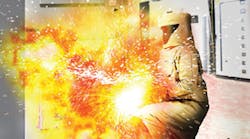
It was the middle of the night when Mr. Brown awoke suddenly to the sound of crackling in his living room. As he entered the hallway to investigate, much to his horror, he saw his motorized treadmill engulfed in flames — with the fire quickly spreading to the nearby furniture. Running past the treadmill and out the door, the man was badly burned. Shielding his face from the heat of the fire, his arms and chest received significant burns that required skin grafts and ultimately a lengthy hospital stay. Although a neighbor called 911, the fire was too intense to go back inside. By the time the fire engines arrived, it was too late to save the other occupants inside. Sadly, the man’s elderly wife and her in-home nurse perished that night in the fire that burned this home to the ground.
The lawsuit
Litigation was filed on behalf of Brown and his family against the treadmill manufacturer as well as others parties, all of whom hired their own respective investigators.
The scene
After the firemen arrived on-site, first on the scene were private fire origin and cause investigators, who usually have plenty of experience as firemen and can determine the location of origin based on burn patterns. In this case, the origin was identified by some of these experts as the treadmill. Others, however, considered additional items in the room as potential sources of ignition, deeming the origin as undetermined. To identify the actual cause, more technical expertise was needed. As a result, all of the “burned up” evidence in the area was photographed, marked, bagged, and secured for later inspection.
The investigation
I was engaged by the insurance company paying the claim. My first assignment was to examine what was left of the treadmill and compare its remains to several new treadmills in order to positively identify the manufacturer. My background is mechanical engineering with expertise in product design, R&D, and safety. As a forensic engineer, I investigate a broad range of issues involving engineering principles.
In this case, the first question I needed to answer was: Who manufactured the treadmill? That answer came relatively easily, because the evidence was persuasive. Once I was certain of the manufacturer, an electrical engineer joined the team. Along with all of the experts hired by outside parties and their lawyers, the evidence was inspected on multiple occasions. X-rays were taken, showing each potential source of ignition in various orientations.
The evidence
Remnants recovered from the scene included anything and everything in the room that possibly could have been a source of ignition, such as electrical appliances, the treadmill, electrical outlets, switches, and wiring. Not surprisingly, after the fire, the condition of the evidence was very poor — so poor, in fact, that nothing much remained of the treadmill’s electrical components. Nevertheless, each of the electrical items was examined, looking for evidence of electrical activity.
Remains of the drive motor and motor driven incline actuator were disassembled. The plastic power supply enclosure was melted away. The power transformer was disassembled. A bit of the power supply circuit board and rectifier remained, with no evidence of a cause. At this point, each of the electrical items in the room could be ruled out as a cause — except the treadmill.
The most likely source of ignition was within the treadmill. By this time, the victim had recovered from his burn injuries sufficiently to describe exactly what he had experienced. Under oath, he testified that he was quite certain that the treadmill was on fire — with fire spreading from the treadmill to the sofa. He spoke at length regarding each of the electrical appliances in the room, describing where they were placed and plugged in. He also recounted the history of the treadmill as well as how and when it was used.
One interesting piece of testimony related to the relocatable power tap (outlet strip) that was located on the floor near the treadmill. It was used occasionally with several appliances, each of which had an on/off switch. He was certain that the power strip was not on fire. The power strip was examined at length and ruled out as a cause.
Digging deeper
Based on study of its design, the treadmill was the only electrical appliance in the room that was powered on continuously. There was an on/off switch on the base, but it was always left in the “on” position. The transformer within the treadmill’s power supply remained powered continuously, making it a candidate for a source of ignition while the treadmill was not being used if there was some kind of electrical failure or malfunction. The treadmill control panel carried low voltage and was protected by fuses. The incline actuator incorporated limit switches to preclude continuous operation. The AC side of the circuit remained a possible candidate for ignition source.
Once the manufacturer was known, several more exemplar treadmills were purchased before a model was found that was an exact match in all respects — mechanically and electrically. While inspecting those exemplar treadmills, the electrical systems were evaluated. There were two different design configurations. The early power supply design, like the one that burned, had a transformer and circuit board with a rectifier and two relays in a plastic housing. The housing was located within the treadmill next to the DC-motorized actuator. The line cord and plug exited at the front of the treadmill and ran along the floor to a wall outlet.
Curiously, in a later version of the same model, the power supply was re-designed and re-located on the treadmill. With a focus on the power pack, both designs were X-rayed and disassembled for internal inspection.
We started with an exemplar of the earlier design. After removing two screws, taking the plastic housing apart, and removing two more screws securing the transformer, the circuit board and wiring were inspected. Testing confirmed the circuit schematic provided by the manufacturer. Various potential failure modes were considered and ruled out.
I then attempted to reassemble the package and found the process to be very awkward. The wiring had to be placed between slots in the case under the transformer before the transformer was nested into the housing on top of the wiring. Then, two long screws were driven through holes in the transformer, sandwiching the AC line cord between the transformer terminals and case. I could not fully tighten the screws without pinching the line cord. The transformer was again removed from the housing without further damaging the line cord.
The culprit
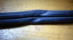
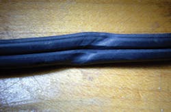
Even though this exemplar power pack had not failed, it exhibited evidence of a design defect. The power cord entered on one end, went through a tortuous path, and terminated on the transformer terminals, where it was squeezed against the plastic housing. The power cord was pinched, leaving indentations in the insulation. These indentations showed evidence of mechanical compression in several spots on the line cord.
During assembly, the line cord must have become pinched as the transformer was assembled into the enclosure (Photo). In this design, once the cord becomes pinched under the transformer, the problem is hidden from view.
Several other exemplar power supplies of the earlier design were examined, each one exhibiting similar evidence of mechanical insult to the line cord insulation at the same location. What if the cord should become twisted or folded over itself at the pinch point? The risk of an unintended electrical path would be even greater.
In my opinion, as well as that of the electrical engineer on the team, the wiring path and packaging design of this power supply was defective. It was also a prime candidate for the cause of this fire. In the later power supply design, the line cord takes a direct path to the transformer, and adequate space is provided for the wiring. The revised design is much easier to assemble, and there is no chance of pinching the wiring during assembly. In the revised design, the wiring can be inspected before final assembly of the enclosure. The design defect was corrected.
Having found the line cords pinched in all exemplars of that type, the electrical engineer and I had a theory of fire causation. A pinched line cord, inside a warm enclosure, powered continuously. Over time, the insulation continued to creep until an unintended conductive path developed.
What was the actual mechanism of insulation failure and establishment of just the right current level for just enough time to ignite plastic and rubber components on the treadmill? That was the subject of much discussion and dispute between the parties. Was there evidence of arcing? If not, why not? Was it arcing through char (i.e., charring of the insulation medium and the subsequent arcing between energized phase conductors and the neutral or ground or both)? Why did it take several years for the failure to occur? Where is the evidence to support this causation scenario?
We believed that under the right conditions, the entire power cord could become an ignition source. The electrical engineer and I felt confident that we had discovered the actual cause of the fire. However, we knew our theory would be challenged. The physical evidence of a conductive path was nowhere to be found, because the smoking gun had been destroyed in the fire or lost in evidence recovery.
To prove that an overheated line cord can ignite the treadmill, we performed a test. We first determined that a current of about 60A was sufficient to make the cord glow orange in about 20 sec to 30 sec, before tripping a 20A circuit breaker. (Breakers were found tripped at the fire scene.)
The manufacturer advised that its materials meet the applicable standard for flammability. To support our theory, we had to try igniting a treadmill. Placing the cord on a carpet below the treadmill, we successfully proved our ignition scenario was viable.
The outcome
In the end, there was an undisclosed settlement with the insurance company recovering some portion of its outlays, and Brown and his family being compensated. The manufacturer never admitted the treadmill was at fault or that the design was revised to correct a defect. Treadmills with the earlier design were not recalled and remain in people’s homes. Under the terms of the settlement, everyone involved is prohibited from discussing further details of the case.
Lessons learned
In this case, a poor mechanical design caused an electrical hazard. The wire became damaged during assembly, as the screws were tightened against the transformer. The damage became hidden from view and was not inspectable. Although this power supply design was reviewed and approved for standards compliance, the hazard was hidden. Therefore, it was not discovered. The revised power supply design corrected the wiring hazard and relocated the power supply on the treadmill, further reducing the likelihood of a fire.
How can we guard against poor designs like this? Techniques for doing formal safety reviews, such as Failure Mode and Effects Analysis (FMEA), are now standard in most industries. For some kinds of products, it’s a matter of law. FMEA, which is easy to learn, is an effective tool for guiding product specifications, design reviews, and following post-manufacture experience in the market. FMEA should be in every design engineer’s toolbox. By asking “What could possibly go wrong?” for every step in a product’s life cycle, potential failures can be eliminated in the design stage.
Was a pinched wire the cause of this fire? Opinions of the various experts were in disagreement. As a forensic engineer, the best we can do is use our knowledge, experience, and judgment to inform our opinion, ethically, responsibly, and to a reasonable degree of engineering certainty.
Leshner is a fellow of the National Academy of Forensic Engineers (NAFE) and board certified in forensic engineering. He can be reached at [email protected].


