Because it integrates power and data transmission in a single cabling structure, offering a number of economic advantages, Power over Ethernet (PoE) is clearly a disruptive development in the construction industry — and well worth learning about. PoE is a technology that allows a local area network (LAN) to carry both data and DC power over twisted-pair, Ethernet cabling (Cat. 5e, 6, 6A, and above cables can be used) to a connected device, such as a wireless access point, an Internet protocol (IP) camera, or a luminaire. PoE first emerged in the year 2000 for powering voice over Internet protocol (VoIP) phones, when Cisco introduced telecommunications equipment that delivered a 48VDC supply over an Ethernet cable for this new type of telephone.
A PoE system consists of power sourcing equipment (PSE), which supplies the power, and the powered device (PD), which receives the power. After an authorization negotiation, a PSE will supply power only to cabling that has a valid PD connected to that cabling. Typically, a PSE is built into an Ethernet switch port, which is called an end-span injection; it can also be a mid-span injection, which is also called a PoE injector. A mid-span injector may typically be used in a lighting space to reduce the cable length and thus minimize power losses. The DC power can be sent on unused conductors of a cable, or it can also be sent on the data conductors by applying a common-mode voltage to each pair of conductors. Because twisted-pair Ethernet uses differential signaling, no interference with data transmission is experienced. The powered device usually receives its DC power via an RJ45 connector.
Recent developments
In the course of a few years, PoE has become widely used to power a host of Ethernet-based products. In June 2003, an Ethernet subcommittee ratified the IEEE 802.3af PoE addenda to deliver up to 13W of DC power over Cat. 3 or Cat. 5 cabling to a device. This is called a Level 1 application. Power can be supplied by two different means (Alternative A and Alternative B), both using two of the cable’s four pairs.
In 2009, a subcommittee ratified the IEEE 802.3at addenda, known as PoE+ or PoE Plus, to deliver up to 25.5W of DC power to a device. This is called a Level 2 application. PoE Plus also raised the minimum performance level to a Cat. 5 cable design.
In 2011, Cisco introduced a non-standard PoE system, called Universal Power over Ethernet, or UPoE, using all four cable pairs to deliver up to 60W to IP phones, compact switches, and wireless access points. In the same year, the HDBase-T Alliance introduced Power over HD Base-T (PoH), for whole home distribution of uncompressed high-definition (HD) multimedia content, 100Mbit/s Ethernet and DC power using all four pairs of Cat. 5e or Cat. 6 cable.
In April 2013, an IEEE 802.3 Task Group developed an addenda, known as 802.3bt, which should be ratified in 2017 or 2018. It offers two new power levels in which all four pairs of a twisted-pair cable are used to deliver the DC power. The first, named PoE++, carries up to 55W to the device, and is called a Level 3 application. The second, named 4PPoE, provides 71W at the device, and is called a Level 4 application. Both levels can support 10GBase-T transmissions. Determining the cabling performance required to support 4-pair delivery of 10Base-T is the task of standards making groups such as the Telecommunications Industry Association (TIA) or ISO/TIA. In a 2014 white paper, one cable manufacturer recommended the use of Cat. 6 or Cat. 6A cabling because higher category cable uses larger gauge sizes and more copper content, allowing reduced cable temperatures.
PoE challenges/solutions
One of the biggest concerns with the application of PoE in a network’s twisted-pair cabling infrastructure is the negative effect of heat build-up in cable bundles as DC power flows through the copper conductors. The conductor resistance (DCR) in PoE cabling is directly related to heat generation. PoE cable bundles dissipate heat until a stable temperature is reached, with the cable bundle having a higher temperature than the surrounding ambient temperature. These elevated temperatures can bring premature aging of jacket material, create bit errors, and cause higher insertion loss, resulting in higher electrical power costs.
The TIA and cable manufacturers offer suggestions to minimize heat gain in large network cable bundles: separate large cable bundles into smaller bundles to reduce heat rise, or specify higher Category-rated cable. The larger conductor sizes in Cat. 6, 6A, and 7A reduce the DC resistance, and thus the power loss in the cable. Additionally, using Cat. 7 S/FTP, which has a foil shield around each pair of conductors, offers superior heat dissipation qualities. Another option is to specify a cable design that uses a foil (but is not grounded) to reduce alien crosstalk. In summary, the factors related to heat generation include the cable type, the number of energized conductor pairs, bundle size (loose lay), ambient air temperature, environmental conditions, the power source, and type of pathway. Other methods to reduce heat build-up in cables include routing cables in well-ventilated pathways, optimizing routing to minimize cable length, and using wire cable trays or similar cable management that allows for largely unrestricted airflow around the cables or cable bundles.
Higher current PoE systems can also cause cumulative damage to RJ-45 connectors in the network. Specifically, when a patch cord is unplugged while the connection is charged, an electrical arc will occur between the connector and the plug. The arcing causes corrosion and pitting damage on the plated contact surface. Cable manufacturers recommend using connectors with 50 µm gold-plated tines, as specified by TIA standards, and using connectors with an all-metal-body construction rather than a plastic-body construction.
Because of these heat-related concerns, the National Fire Protection Association (NFPA), Underwriter’s Laboratories (UL), TIA, BICSI, and other organizations continue to work on the effects of heat on DC-powered communications cabling. Although previous versions of the National Electrical Code (NEC) did not specifically deal with PoE systems, the 2017 Edition addresses this heat build-up concern in Sec. 840.160. “Communications cables, in addition to carrying the communications circuit, shall also be permitted to carry circuits for powering communications equipment. Where the power supplied over a communications cable to communications equipment is more than 60W, communications cable and the powering circuits shall comply with 725.144 where communications cables are used in place of Class 2 and
Class 3 cables.”
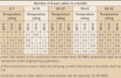
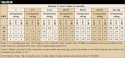
Since the NEC deals with conductor heating by the use of ampacity tables, the first option in determining a suitable cable type for PoE is to consult the ampacity table in Sec. 725.144 (see the Table). This Table recognizes the relationship between AWG size, bundle size, and the temperature rating to determine the current-carrying capacity of the cable. For example, a cable with 23 AWG conductors and rated for 75°C can accommodate 0.7A in a bundle up to 91 cables.
The 2017 Edition of the Code makes clear that data/com cable must have a temperature rating of at least 60°C (140°F) as mentioned above, and have the temperature rating marked on the cable jacket if the rating exceeds 60°C [Sec. 840.160]. The 2017 NEC also introduces another classification: limited power (LP) cables (the cable legend to include “…CMP-LP(O x A).” The LP cable marking is a new and entirely optional cable designation for communications cables, and the designation means that the cable can carry the marked current for each conductor without exceeding the temperature rating of the cable. LP cable uses TSB-184-A to determine bundle size. If a cable project is designed for a Type 4 PoE installation, an LP-listed cable rated for at least 0.5A should be used.
Low-voltage lighting installations that are not fully Ethernet-switch-enabled systems, and perhaps using different wire sizes (such as 18 AWG cable) are also being designed and installed. These systems generally use a ceiling plenum-mounted chassis, fitted with a number of ports, or channels, that each transmits low-voltage power over Category cable to luminaires or dimmer switches. The communications scheme and architecture is extremely flexible and scalable. Any LED luminaire can be connected to any chassis, and multiple chassis can be grouped in a cluster and connected to the customer’s data network. At the 2016 Lightfair International show, a major luminaire manufacturer showed a distributed low-voltage power (DLVP) architecture that includes 300W and 600W DC power units and a rugged and versatile structured cabling system. Multiple 100W channels can be daisy-chained to power at least four luminaires.
Who is qualified to install a PoE system?
Because PoE is a fairly new concept and could disrupt the lighting industry more than the LED revolution, uncertainty exists on how electrical inspectors will judge these installations. In fact, PoE threatens to move lighting from the electrical domain to the IT department. This is why major IT players see themselves as stakeholders. Most likely, each state and local authority having jurisdiction (AHJ) will have their own interpretation of these systems. Therefore, installing contractors should consult with the local AHJ on all details relating to the latest PoE installation requirements.
Editor’s Note: The presentations of Brett Hansen of Leviton Network Solutions and Frank Straka of Panduit Corp. at the 2016 BICSI Fall Conference were referenced in the preparation of this article.
About the Author
Joseph R. Knisley
Lighting Consultant
Joe earned a BA degree from Queens College and trained as an electronics technician in the U.S. Navy. He is a member of the IEEE Communications Society, Building Industry Consulting Service International (BICSI), and IESNA. Joe worked on the editorial staff of Electrical Wholesaling magazine before joining EC&M in 1969. He received the Jesse H. Neal Award for Editorial Excellence in 1966 and 1968. He currently serves as the group's resident expert on the topics of voice/video/data communications technology and lighting.

