If you work with electric motors and pumps, you’ll eventually encounter a pump curve and one of its key parameters — best efficiency point (BEP). The BEP is the point on the curve where the pump operates most efficiently. Unique to each pump, the BEP is a product of both impeller design and several related pump curve parameters.
Pump efficiency
Electric motor efficiency varies with load and peaks at about 75% of full load. Pump efficiency is more complex, as it varies with both the head and flow rate of the pump. In fact, efficiency, head, flow rate, and power are interdependent and described by the equation:
BHP = [(Q × H) ÷ (3,960 × n)] × s.g.
Where:
BHP = brake horsepower
Q = flow rate (gallons per minute)
H = head (feet)
h = efficiency
s.g.= specific gravity (remains constant)
The power to drive a pump is an important consideration when designing new installations or troubleshooting existing ones. Power is inversely proportional to efficiency, so pumps use less of it when operating more efficiently.
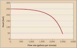
Power is also directly proportional to the flow rate times the head (Q × H), both of which vary with demand in a rotodynamic pump system. Restricting system discharge (e.g., by closing a throttle valve) will therefore reduce flow and increase head, whereas opening the valve will increase flow and reduce head. This same basic relationship between head and flow rate will apply for the curve of each specific pump (Fig. 1).
Effect of flow rate
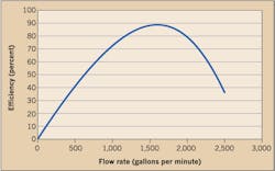
To understand BEP, be aware that flow rate through a rotodynamic pump varies from zero at “dead head” (discharge valve closed) to maximum at “run out” condition (no discharge restriction). Pump efficiency is thus a function of flow through the pump, although it isn’t strictly linear (Fig. 2).
Imagine the flow of traffic on a highway with efficiency measured as cars per minute. Late at night when no cars are on the road (i.e., no traffic), efficiency is zero — and very low early in the morning when few cars are traveling. During rush hour, as volume rapidly increases, bottlenecks form, traffic slows to a crawl, and efficiency plummets. However, just before rush hour, there’s usually a time with lots of fast-moving traffic when the highway handles the most cars per minute (i.e., its BEP).
Related
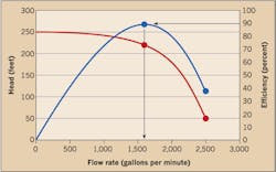
The BEP for a pump is similar (Fig. 3). With the discharge valve closed (“dead head”) and zero flow, efficiency is zero. Opening the valve will reduce the discharge restriction, so flow through the pump and efficiency will gradually increase until it becomes more turbulent. At that point, efficiency will start dropping and continue to drop as the pump approaches “run out” condition. As with traffic flow on a busy highway, somewhere between “dead head” and “run out” condition, the flow rate will be at maximum efficiency (i.e., the BEP).
Note that the BEP in Fig. 3 occurs at a flow rate of about 1,600 units, which coincides with the maximum value on the efficiency curve. That flow rate also intersects the pump curve at a point equal to head of about 220 units.
If pump efficiency changes with flow rate, it’s logical to ask why. As noted earlier, one reason is that pump efficiency directly correlates with turbulence in the flow (i.e., the lower the turbulence, the greater the efficiency). Therefore, the BEP is where turbulence is minimal.
Effect impeller design on BEP
Impeller design is the most significant factor for determining the BEP of a pump, because it dictates how efficiently power (brake horsepower or BHP) is transmitted to the liquid being pumped (“pumpage”). A properly designed impeller optimizes flow while minimizing turbulence.
Pumpage enters the impeller eye and accelerates as it travels radially outward through the impeller toward the impeller discharge. As the liquid discharges from the impeller, it merges with the liquid already in the impeller housing. If the impeller vanes are at just the right angle relative to the rate of flow, the incoming pumpage will merge smoothly with the swirling pumpage in the housing, minimizing turbulence, maximizing efficiency, and yielding the BEP for that impeller.
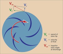
Design engineers calculate the impeller vane angle for a certain flow rate using a series of vectors. As Fig. 4 shows, vector Vt represents the speed of the vane tip (tangent and relative to the impeller), and Vr represents the radial velocity of the pumpage flowing out of the impeller. The discharge angle of the flow is Vm (the sum of vectors Vt and Vr), which should match the impeller vane angle at the discharge. The length of vector Vr changes with flow rate, so greater flow through the pump means the pumpage must move faster as it exits the impeller.
Note that the flow rate changes the discharge angle, but the impeller vane angle remains constant. The BEP is the flow rate where the discharge angle matches the vane angle. Similar design factors apply to the impeller intake. Although impeller housing characteristics also play a role, the impeller design is the primary factor that determines the flow rate at which the BEP occurs.
The most important thing to remember from this discussion is that any modification of the impeller will change the pump’s BEP. Trimming the outside diameter (OD) of an impeller, replacing an impeller with one of different diameter or number of vanes, or changing the rotating speed of the impeller will alter the BEP. Before modifying an impeller or its rotating speed in any way, be sure to determine how the change will impact the pump curve, the efficiency curve, and the BEP.
Vogel is a pump and vibration specialist at the Electrical Apparatus Service Association, Inc. (EASA) in St. Louis. He can be reached at [email protected].
