Courtesy of www.MikeHolt.com.
This article is the ninth in a 12-part series on the differences between grounding and bonding.
Chapter 4 [Equipment for General Use] helps you apply Art. 250 to installations involving general equipment. Five Articles are of particular interest:
- Article 404 — Switches. The requirements apply to switches of all types, such as snap switches, dimmer switches, circuit breakers, fused and non-fused safety switches, and automatic timer switches.
- Article 406 — Receptacles and Attachment Plugs (Caps). This article covers the rating, type, and installation of receptacles and attachment plugs (cord caps).
- Article 408 — Switchboards and Panelboards. The requirements apply to switchboards, panelboards, and distribution boards that supply lighting and power circuits.
- Article 410 — Luminaires, Lampholders, and Lamps. Because of the many types and applications of luminaires, this Article is extensive.
- Article 440 — Air-Conditioning and Refrigeration Equipment. Article 440 applies to electrically driven air-conditioning and refrigeration equipment with a hermetic compressor motor.
Article 404 ― Switches
The metal mounting yokes for switches, dimmers, and control switches must connect to an equipment grounding conductor. Metal faceplates must be bonded to the equipment grounding conductor (EGC) [Sec. 404.9(B)].
Snap switches, dimmers, control switches, and metal faceplates are considered connected to an EGC using either of the following methods:
(1) Metal boxes. The switch is mounted with metal screws to a metal box or a metal cover that is connected to an EGC per Sec. 250.148.
Direct metal-to-metal contact between the device yoke of a switch and the box is not required. The switch is connected to the effective ground-fault current path when the yoke is mounted with metal screws to a metal box (Fig. 1).

(2) Nonmetallic boxes. The grounding terminal of the switch yoke must connect to the circuit EGC.
Exception No. 1: Where no means exist within the box for bonding to an EGC, or if the wiring method at the existing switch does not contain an EGC, a switch without such a connection to the EGC is permitted for replacement purposes only. A switch installed under this exception must have a nonmetallic faceplate with nonmetallic screws, or the replacement switch must be GFCI-protected.
Exception No. 2: Listed assemblies are not required to be bonded to an EGC if all four conditions in this exception are met. For example, the device has a nonmetallic yoke.
Exception No. 3: An EGC is not required for bonding a snap switch with an integral nonmetallic enclosure complying with Sec. 300.15(E).
Metal enclosures for switches and circuit breakers must be connected to an EGC of a type recognized in Sec. 250.118 [Sec. 250.4(A)(3)]. Where nonmetallic enclosures are used with metal raceways or metal-armored cables, they must comply with Sec. 314.3 Exception No. 1 or Exception No. 2 [Sec. 404.12].
Article 406 ― Receptacles and Attachment Plugs (Caps)
Receptacles of the isolated EGC type must be identified by an orange triangle marking on the face of the receptacle [Sec. 406.3(D)].
Isolated ground receptacles must have the grounding contact of the receptacle connected to an insulated EGC installed with the circuit conductors, per Sec. 250.146(D) [Sec. 406.3(D)(1)].
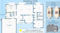
Receptacles installed on 15A and 20A branch circuits must be of the grounding type, except as permitted for 2-wire receptacle replacements as permitted in Sec. 406.4(D)(2) [Sec. 406.4(A)] (Fig. 2).

The EGC contacts of receptacles and cord connectors must be connected to the EGC of the circuit supplying the receptacle or cord connector [Sec. 406.4(C)].
The branch-circuit wiring method must include or provide an EGC to which the EGC contacts of the receptacle or cord connector are connected. See Sec. 250.118 for acceptable types of EGCs.
If the receptacle to be replaced is in a location that requires an AFCI- and/or GFCI-type receptacle, the replacement receptacle must be installed at a readily accessible location [Sec. 406.4(D)].
If an EGC exists in an outlet box, each replacement receptacle must be of the grounding-type, and the receptacle’s grounding terminal must be connected to the circuit EGC per Sec. 406.4(C) [Sec. 406.4(D)(1)].
If an EGC does not exist in the outlet box, a replacement receptacle can be a [Sec. 406.4(D)(2)]:
(a) Nongrounding-type receptacle.
(b) GFCI-type receptacle if the receptacle or the cover plate is marked “No Equipment Ground.” An EGC is not required from the GFCI-type receptacle to any receptacle outlets downstream.
(c) GFCI-protected grounding-type receptacle if the receptacle or the cover plate is marked “GFCI Protected” and “No Equipment Ground.” An EGC is not required from the GFCI-protected grounding-type receptacle to any receptacle outlets downstream (Fig. 3).
GFCI protection functions properly on a 2-wire circuit without an EGC because the circuit’s EGC serves no role in the operation of a GFCI device.
Metal faceplates for receptacles must be connected to the circuit EGC [Sec. 406.6(B)]. The grounding terminal of receptacles must be connected to an EGC per Sec. 250.146 [Sec. 406.11].

Article 408 ― Switchboards and Panelboards
Metal cabinets containing panelboards must be connected to an EGC of a type recognized in Sec. 250.118 [Sec. 215.6 and Sec. 250.4(A)(3)]. Where a panelboard cabinet contains EGCs of the wire type, a terminal bar for them must be installed and bonded to the metal cabinet [Sec. 408.40].
EGCs cannot terminate on the neutral terminal bar except as permitted by Sec. 250.142(A) for services and separately derived systems.
Many panelboards are rated for use as service disconnects, which means they are supplied with a main bonding jumper [Sec. 250.28]. This screw or strap is not permitted to be installed except when the panelboard is used for a service disconnect [Sec. 250.24(A)(5)] or a separately derived system [Sec. 250.30(A)(1)].
Article 410 ― Luminaires, Lampholders, and Lamps
Because of the many types and applications of luminaires, manufacturers’ instructions are important and helpful for proper installation. UL produces a pamphlet called the Luminaire Marking Guide, which provides information for properly installing common types of incandescent, fluorescent, and high-intensity discharge (HID) luminaires.
Metal poles used for the support of luminaires must be connected to an EGC of a type recognized in Sec. 250.118 [Sec. 250.4(A)(5)]. Because the contact resistance of an electrode to the earth is so high, very little fault current returns to the power supply if the earth is the only fault current return path. As a result, the circuit overcurrent protective device (OCPD) will not open and clear the ground fault, and the metal pole will become and remain energized by the circuit voltage.
Luminaires and lighting equipment must be connected to the circuit EGC as required in Art. 250 and Part V of this Article [Sec. 410.40].
The metal parts of luminaires must be connected to an EGC of a type recognized in Sec. 250.118 [Sec. 410.44].
Exception No. 1: Replacement luminaires may connect an EGC in the same manner as replacement receptacles in compliance with Sec. 250.130(C). The luminaire must then comply with Sec. 410.42.
Exception No. 2: Where no EGC exists at the outlet, replacement luminaires that are GFCI-protected or do not have exposed conductive parts are not required to be connected to an EGC.
Luminaires with exposed metal parts must be provided with a means for connecting an EGC [Sec. 410.46]. Lighting equipment identified for horticultural use must be connected to the circuit EGC as required in Art. 250 and Part V of this Article [Sec. 410.182].
Article 440 ― Air-Conditioning and Refrigeration Equipment
Where air-conditioning or refrigeration equipment is installed on a roof and connected with a metallic raceway, an EGC of the wire type must be installed within the outdoor portion of the metallic raceway systems that use compression-type fittings [Sec. 440.9].
When the wiring method for rooftop units is not a threaded type system, you cannot rely on the raceway to serve as the EGC as permitted by Sec. 250.118 and must install an appropriately sized wire-type EGC instead.
Metal raceway systems with compression fittings could be subjected to movement and physical damage from roof activities such as snow removal or a roof repair/replacement. The installation of a wire-type EGC provides reassurance of the effective ground-fault current path in case of a ground fault at the air-conditioning or refrigeration equipment.
Error prevention
If you meticulously apply the Chapter 4 requirements on the general equipment you are installing, one result is you move that entire installation toward conformance with the grounding and bonding requirements of Art. 250.
A good way to prevent errors is to consider each metal object and review how it connects to the EGC (or not). For example, all of your switches have metal faceplates. If those switches are mounted in nonmetallic boxes, you need to ensure the grounding terminal of each switch yoke connects to the EGC.
If the drawings inadvertently leave out one or more of the requirements we have just discussed, this type of review should catch the omissions.
These materials are provided to us by Mike Holt Enterprises in Leesburg, Fla. To view Code training materials offered by this company, visit www.mikeholt.com/code.