Courtesy of www.MikeHolt.com. Based on the 2020 NEC.
Article 725 of the National Electrical Code (NEC) covers remote-control, signaling, and power-limited circuits that are not integral to a device or appliance. This includes circuits for burglar alarms, access control, sound, nurse call, intercoms, some computer networks, some lighting dimmer controls, and some low-voltage industrial controls.
Here are some examples of the three types of circuits:
- A remote-control circuit controls other circuits through a relay or solid-state device. A motion-activated security lighting circuit is an example of this.
- A signaling circuit provides an output that is a signal or indicator such as a buzzer, flashing light, or annunciator.
- A power-limited circuit is a circuit supplied by a transformer or other electric power source that limits the amount of power to provide safety from electrical shock and/or fire ignition.
Article 725 circuits “are characterized by usage and power limitations that differentiate them from electrical power circuits” [Sec. 725.1 Note]. It provides alternative requirements for minimum conductor sizes, overcurrent protection, insulation requirements, wiring methods, and materials.
Article 725 consists of four parts. Part I provides general requirements (which we address here), Part II pertains to Class 1 circuits (which we also address here), Part III pertains to Class 2 circuits, and Part IV provides listing requirements.
Class 1 vs. Class 2:
- Class 1 circuit. The wiring system between the load side of a Class 1 circuit overcurrent protective device (OCPD)and the connected equipment. See Sec. 725.41 for the voltage and power limitations of Class 1 circuits.
- Class 2 circuit. The portion of the wiring system between the load side of a Class 2 power supply and the connected Class 2 equipment. Due to the limitations of its power supply, a Class 2 circuit is considered safe from a fire initiation standpoint and provides acceptable electric shock protection.
General requirements
An understanding of the general requirements is necessary to correctly install Class 1 or Class 2 circuits.
Article 725 consists of “Other Article” requirements found in Sec. 725.3(A) through (P). These aren’t referencing exceptions to Art. 725 that are covered elsewhere. These are requirements in addition to the requirements of Art. 725.
The number and size of conductors or cables within a raceway are limited per Sec. 300.17 [Sec. 725.3(A)]. Raceways must be large enough to permit the installation and removal of conductors without damaging conductor insulation [Sec. 300.17].
When all conductors within a raceway are the same size and insulation, the number of conductors permitted can be found in Annex C for the raceway type [Chapter 9, Notes to Tables, Note 1].
For conductors not included in Chapter 9 (such as a multiconductor cable) you must use the actual dimensions. If you use one multiconductor cable inside a raceway, you must use the single conductor percentage fill area [Chapter 9, Notes to Table, Notes 5 and 9].
To limit the spread of fire or products of combustion, the installation of Class 1 and Class 2 circuits must comply with Sec. 300.21 [Sec. 725.3(B)]. Electrical circuits and equipment must be installed in such a way that the spread of fire or products of combustion will not be substantially increased. Openings into or through fire-resistive walls, floors, and ceilings for electrical equipment must be fire-stopped using methods approved by the authority having jurisdiction (AHJ) to maintain the fire-resistance rating of the fire-resistive assembly [Sec. 300.21].
Outlet boxes must have a horizontal separation of at least 24 in. when installed on opposite sides in a fire-resistive assembly unless an outlet box is listed for closer spacing or protected by fire-resistant “putty pads” per manufacturer’s instructions. “Putty pads” are typically installed on the exterior of the box, but many manufacturers have listed inserts for box interiors.
Boxes installed in fire-resistive assemblies must be listed for the purpose. If steel boxes are used, they must be secured to the framing member. Cut-in-type boxes are not permitted.
Class 1 and Class 2 circuits installed in ducts or plenums must comply with Sec. 300.22. [Sec. 725.3(C)]
Exception No. 1: Class 2 cables selected per Table 725.154 and installed per Sec. 725.135(B) and Sec. 300.22(B), Exception, can be installed in ducts specifically fabricated for environmental air.
Exception No. 2: Class 2 cables selected per Table 725.154 and installed per Sec. 725.135(C) can be installed in plenum spaces.
Class 1 and Class 2 circuits installed in hazardous (classified) locations must comply with the following Sections: 501.10(B)(1), 501.150, 502.10(B)(1), 502.150, 503.10(A)(1), 503.150, 506.15(A), 506.15(C), 511.7(B)(1), 515.7(A). They must also comply with Art. 517, Part IV [Sec. 725.3(D)].
Class 1, 2, and 3 circuits in cable trays must be installed per Parts I and II of Art. 392 [Sec. 725.3(E)].
If a raceway is subjected to different temperatures, and where condensation is a known problem, per Sec. 300.7(A) you must fill the raceway with a material approved by the AHJ to prevent the circulation of warm air to a colder section of the raceway [Sec. 725.3(H)]. This raceway seal is not the same thing as an explosion-proof seal.
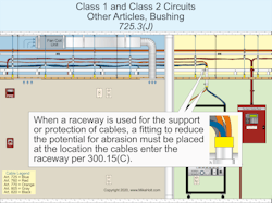
When a raceway is used for the support or protection of cables, a fitting is required to reduce the potential for abrasion and must be placed where the cables enter the raceway per Sec. 300.15(C) [Sec. 725.3(J)], as shown in Fig. 1.
Equipment grounding conductors must be identified per Sec. 250.119 [Sec. 725.3(P)].
Exception: Conductors with green insulation are permitted to be used as ungrounded signal conductors for Types CL3P, CL2P, CL3R, CL2R, CL3, CL2, CL3X, CL2X, and substitute cables installed per Sec. 725.154(A).
Above suspended-ceiling panels, ensure there’s not an accumulation of cables that prevents the removal of those panels for access to equipment [Sec. 725.21].
Exposed cables must be supported by the structural components of the building, so they will not be damaged by normal building use. Support must be by straps, staples, hangers, cable ties, or similar fittings designed and installed in a manner that will not damage the cable [Sec. 725.24].
Cables installed through or parallel to framing members or furring strips must be protected where they are likely to be penetrated by nails or screws. Do this by installing the wiring method so it is at least 1¼ in. from the nearest edge of the framing member or furring strips, or by protecting it with a 1⁄16-in.-thick steel plate or equivalent [Sec. 300.4(D)].
Circuits used for safety-control equipment must be classified as Class 1 if the failure of the remote-control circuit or equipment introduces a direct fire or life hazard [Sec. 725.31(A)].
Class 1 circuit requirements
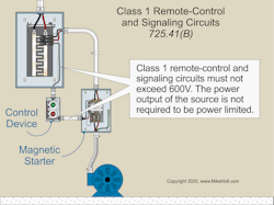
Class 1 power-limited circuits must be supplied from a power supply that limits the output to 30V and no more than 1,000VA [Sec. 725.41(A)]. Class 1 remote-control and signaling circuits must not exceed 600V; the power output of the source need not be power limited Sec. 725.41(B)], as shown in Fig. 2.
Overcurrent protection for conductors 14 AWG and larger must be based on the conductor ampacity per Sec. 110.14(C)(1) and Table 310.16. Overcurrent protection for 18 AWG conductors cannot exceed 7A; and for 16 AWG conductors, overcurrent protection cannot exceed 10A [Sec. 725.43].
Locate OCPDs at the point where the conductor to be protected receives its supply [Sec. 725.45(A)].
Class 1 circuit conductors supplied by a transformer having only a 2-wire secondary can be protected by the primary OCPD per Sec. 450.3(B), but only if the primary OCPD does not exceed the value determined by multiplying the secondary conductor ampacity by the secondary-to-primary transformer voltage ratio [Sec. 725.45(D)].
Class 1 circuits must be installed per Part I of Art. 300, and Class 1 wiring must be installed in a suitable Chapter 3 wiring method [Sec. 725.46].
Two or more Class 1 circuits can be installed in the same cable, enclosure, or raceway if all conductors are insulated for the maximum voltage of any conductor [Sec. 725.48(A)]. Class 1 circuits can be installed with electrical power conductors under any of the circumstances described in Sec. 725.48(B)(1) through (4).
Conductors of sizes 18 AWG and 16 AWG installed within a raceway, enclosure, or listed cable are permitted if they do not supply a load that exceeds the ampacities of Table 402.5. Conductors 14 AWG and larger must meet the ampacities of Table 310.16 [Sec. 725.49(A)]. Class 1 circuit conductors must have at least a 600V insulation rating [Sec. 725.49(B)].
Avoiding Code violations with Class 1 installations
The key to understanding and correctly applying Art. 725 is in knowing the voltage and energy levels of the circuits, the wiring method involved, and the purpose(s) of the circuit. Many of the installation errors with these systems arise from failing to properly characterize the installation. Take the time to ensure each circuit is properly identified whether it is Class 1, 2, or 3. If it is Class 1, determine whether it is power-limited or not. In addition to the general requirements, apply the relevant requirements for that Class and type of circuit.
These materials are provided to us by Mike Holt Enterprises in Leesburg, Fla. To view Code training materials offered by this company, visit www.mikeholt.com/code.
