Article 406 covers the rating, type, and installation of receptacles and attachment plugs. It also covers flanged surface inlets [Sec. 406.1], as shown in Fig. 1.

With the 2023 revision, the definitions that previously appeared in Sec. 406.2 have been moved to Art. 100. Here are two that are important to know:
- Child Care Facility. A building (or portions thereof) used for educational, supervision, or personal care services for five or more children seven years in age or less.
- Outlet Box Hood. A housing shield (hood) over a faceplate for flush-mounted wiring devices, or an integral component of an outlet box or faceplate for flush-mounted wiring devices, commonly known as a “while in use” or “bubble” cover.
In regards to receptacle rating and types, they:
- Must be listed and marked with the manufacturer’s name or identification and voltage and ampere ratings [Sec. 406.3(A)].
- Of the isolated equipment grounding conductor (EGC) type must be identified by an orange triangle marking on the face of the receptacle [Sec. 406.3(E)]. Isolated ground receptacles must have the grounding contact of the receptacle connected to an insulated EGC installed with the circuit conductors.
- That are nonlocking, 15A or 20A, 125V, and automatically controlled to remove power for energy management or building automation must be permanently marked with the word “controlled” and sport a visible power symbol after installation [Sec. 406.3(F)]. The marking is not required for wall switch-controlled receptacles used for lighting in a dwelling [Sec. 210.70(A)(1), Exception 2].
General installation requirements
Receptacles installed on 15A and 20A branch circuits must be of the grounding type [Sec. 406.4(A)].
The EGC contacts of receptacles and cord connectors must be connected to the equipment grounding conductor (EGC) of the circuit supplying the receptacle or cord connector per Sec. 250.146 [Sec. 406.4(C)].
The branch-circuit wiring method must include or provide an EGC to which the EGC contacts of the receptacle or cord connector are connected.
Note 1: See Sec. 250.118 for acceptable grounding means.
Replacements
If an EGC exists in an outlet box, replacement receptacles must be of the grounding type, and the receptacle’s grounding terminal must be connected to the circuit EGC per Sec. 406.11 [Sec. 406.4(D)(1)].
If an EGC does not exist in the outlet box, replacement receptacles can be: [Sec. 406.4(D)(2)]:
(a) Nongrounding-type receptacles.
(b) GFCI-type receptacles if the receptacle or the cover plate is marked “No Equipment Ground."
(c) GFCI-protected grounding-type receptacles if the receptacle or the cover plate is marked “GFCI Protected” and “No Equipment Ground."
GFCI protection functions properly on a 2-wire circuit without an EGC because the EGC serves no role in the operation of a GFCI device.
The permission to replace nongrounding-type receptacles with GFCI-protected grounding-type receptacles does not apply to new receptacle outlets that extend from an existing outlet box not connected to an EGC.
When existing receptacles are replaced in locations where GFCI protection is required, the replacement receptacles must be GFCI protected [Sec. 406.4(D)(3)].
Exception: Where the outlet box size will not permit the installation of the GFCI receptacle, a GFCI-protected grounding-type receptacle marked “GFCI Protected” and “No Equipment Ground” per Sec. 406.4(D) is permitted.
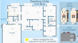
See Sec. 210.8 for specific locations requiring GFCI protection. Where an NEC rule requires GFCI protection, you can provide that with a GFCI circuit breaker, GFCI receptacle, or a non-GFCI receptacle downstream of a feed-through type GFCI receptacle.
When existing receptacles are replaced in locations where:
- Tamper resistance is required [Sec. 406.12], replacement receptacle(s) must be listed tamper resistant [Sec. 406.4(D)(5)].
- Weather resistance is required, replacement receptacles must be weather resistant [Sec. 406.4(D)(6)].
- AFCI protection is required [Sec. 210.12], replacement receptacle(s) must be one of the following [Sec. 406.4(D)(4)]:
(1) Listed AFCI receptacle.
(2) Receptacle protected by a listed AFCI receptacle.
(3) Receptacle protected by a listed combination type AFCI circuit breaker.
Receptacles must be provided with GFPE where replacements are made at receptacle outlets that are required to be GFPE protected per Sec. 555.35(B)(1) [Sec. 406.4(D)(8)], as shown in Fig. 2.
(1) contains requirements for GFPE protection of receptacles.")
Mounting Receptacles
Receptacles must be installed in outlet boxes that (unless otherwise permitted in the Code) are securely fastened in place [Sec. 406.5]. Boxes containing a hub can be supported from a flexible cord connected to fittings that prevent tension from being transmitted to joints or terminals [Sec. 400.14 and Sec. 314.23(H)(1)].
Screws used for attaching a receptacle to a box must be a type provided with a listed receptacle or be machine screws having 32 threads per inch.
Faceplates must completely cover the outlet openings [Sec. 406.6]. Metal faceplates for receptacles must be connected to the circuit EGC [Sec. 406.6(B)].
- In outlet boxes set back from the finished surface must be installed so the mounting yoke of the receptacle is held rigidly to the finished surface [Sec. 406.5(A)].
- In walls or ceilings of noncombustible material (such as drywall) outlet boxes must not be set back more than ¼ in. from the finished surface. In walls or ceilings of combustible material, outlet boxes must be flush with the finished surface [Sec. 314.20]. There must not be any gaps more than 1⁄8 in. at the edge of the outlet box [Sec. 314.21].
- In outlet boxes that are flush with the finished surface must be installed so the mounting yoke of the receptacle is held rigidly against the outlet box or raised box cover [Sec. 406.5(B)].
- Supported by a cover must be held rigidly to the cover with at least two screws [Sec. 406.5(C)].
- Must be flush with, or project from, the faceplates [Sec. 406.5(D)].
- Installed in countertop surfaces must be listed for countertop applications [Sec. 406.5(E)].
- Listed for work surfaces or countertops can be installed in a work surface [Sec. 406.5(F)].
- Must not be installed in a face-up position in or on countertop surfaces or work surfaces unless listed for countertop surface or work surface applications [Sec. 406.5(G)(1)].
- Must not be installed in a face-up position in the area below a sink [Sec. 406.5(G)(2)].
- Must not be in enclosures with other switches or receptacles if the voltage between the devices exceeds 300V, unless the devices are installed in enclosures equipped with barriers (identified for the purpose) that are securely installed between adjacent devices [Sec. 406.5(J)].
Attachment Plugs and Flanged Surface Inlets
Attachment plugs and flanged surface inlets must be listed for their purpose.
Attachment plugs must be installed so their prongs, blades, or pins are not energized unless inserted into an energized receptacle or flexible cord. A flanged surface inlet must be installed so the prongs, blades, or pins are not energized unless an energized cord connector is inserted into the inlet (Fig. 3).
.")
Damp or wet locations
In addition, 15A and 20A receptacles installed in a wet location must be within an enclosure that is weatherproof when an attachment plug is inserted using an outlet box hood identified as “extra duty” [Sec. 406.9(B)(1)]. Hinged covers of outlet box hoods must be able to open at least 90º or fully open (if the cover is not designed to open 90º from the closed to open position) after installation.
Nonlocking-type 15A and 20A receptacles in a wet location must be listed as the weather-resistant type. Receptacles rated 30A or more installed in a wet location must comply with Sec. 406.9(2)(a) or (b).
Tamper-Resistant
Getting it right every time
These materials are provided by Mike Holt Enterprises in Leesburg, Fla. To view Code training materials offered by this company, visit www.mikeholt.com/code.