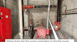
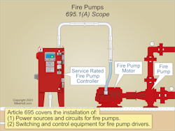
A general philosophy for most electrical installations is to provide circuit protection that will disconnect power before allowing the conductors to overheat and become damaged. Article 695 departs from this philosophy (see Fig. 1).
A fire pump motor must keep running no matter what because it supplies water to a facility’s fire protection piping. The requirements for ensuring that ability extend well beyond the NEC. But if you don’t at least meet the NEC requirements, you won’t gain that ability.
Electric power source(s)
Power to fire pump motors must be supplied by a reliable source with the capacity to carry the locked-rotor current of the fire pump motor(s), pressure maintenance pump (“jockey pump”) motors, and the full-load current of any associated fire pump equipment [Sec. 695.3(A)].
Permitted reliable power sources include:
(1) Separate Remote Service. A separate service for the fire pump that is remote from the normal service to minimize unintentional interruption [Sec. 230.72(B)]. Or a connection ahead of, but not within, the service disconnecting means [Sec. 230.82(5)].
To minimize unintentional interruption, the service disconnect for the fire pump system must be remote from the normal power system service disconnects [Sec. 230.72(B)]. Generally, the pump conductor tap termination point is situated ahead of the main service disconnect(s), and the fire pump disconnect is within sight of the fire pump itself.
(2) On-Site Power. An on-site power generator located and protected to minimize damage by fire. See NFPA 20, Standard for the Installation of Stationary Pumps for Fire Protection, for guidance in determining electric power source reliability.
If reliable power cannot be obtained from a source described in Sec. 695.3(A), power must be supplied by one of the following:
(1) Individual Sources. A combination of two or more of the individual sources from Sec. 695.3(A) and approved by the authority having jurisdiction (AHJ).
(2) Individual Source and On-Site Standby Generator. A combination of one of the sources in Sec. 695.3(A) and a generator complying with Sec. 695.3(D) and approved by the AHJ.
Exception to (1) and (2): An alternate source of power is not required where a backup, engine, steam turbine, or electric motor-driven fire pump with an independent power source complying with
Sec. 695.3(A) or (C) is installed.
Transfer of power to the fire pump controller must take place within the pump room [Sec. 695.3(F)]. A single means of disconnect is permitted between the fire pump electric supply and a fire pump controller, power transfer switch, or controller/power transfer switch (each of which must be listed), per Sec. 695.4(B)(1)(a). The overcurrent protective device(s) must have an ampere rating to carry indefinitely the sum of the locked-rotor current of the largest fire pump motor and 100% of the full-load current of the other pump motors and fire pump’s accessory equipment [Sec. 695.4(B)(2)(a)(1)].
Overcurrent protection
Overcurrent protection must be listed for fire pump service [Sec. 694.(B)(2)(a)(2)]. It cannot have a field-adjustable trip setting. It cannot open:
- Within 2 minutes at 600% of the full-load current of the pump motor(s).
- With a re-start locked-rotor current of 24 times the full-load current of the pump motor(s).
- Within 10 minutes at 300% of the full-load current of the pump motor(s).
Overcurrent protective devices between an on-site standby generator and a fire pump controller must be sized per Sec. 430.62, based on the largest rating or setting of the short-circuit and ground-fault device for the largest motor FLC and the sum of other motors on the feeder [Sec. 695.4(B)(2)(b)].
Transformers
If a transformer supplies an electric fire pump motor, size it at least 125% of the sum of the fire pump motor(s) and jockey pump(s) motor loads, and 100% of the ampere rating of the fire pump’s accessory equipment [Sec. 695.5(A)].
Size the primary overcurrent protective device(s) to carry indefinitely the sum of the locked-rotor current of the fire pump motor(s) and jockey pump motor(s), and 100% of the ampere rating of the fire pump’s accessory equipment. Secondary overcurrent protection is not permitted. The requirement to carry the locked-rotor current indefinitely does not apply to fire pump motor conductors [Sec. 695.5(B)].
Services
Service conductors and conductors supplied by on-site power production must be physically routed outside buildings and installed as service conductors per Sec. 230.6, Sec. 230.9, and Parts II and III of Art. 230 [Sec. 695.6(A)(1)]. Where such routing isn’t possible, they can be routed through buildings per Sec. 230.6(1) or (2).
Feeders
Fire pump controller supply conductors on the load side of the final disconnecting means and overcurrent device(s) permitted by Sec. 695.4(B) or conductors that connect directly to an on-site standby generator must comply with all of Sec. 695.6(A)(1) through (4). For example, the conductors must be kept independent of all other wiring.
With the 2023 revision, six Informational Notes were added. There are actually only five because Informational Notes 2 and 5 contain the identical text. Four of the five are references to specific UL standards.
Conductor ampacity
Conductors supplying a fire pump motor(s), jockey pump(s), and associated fire pump accessory equipment must have a minimum ampacity of at least the sum of the following [Sec. 695.6(B)(1)]:
(1) 125% of the sum of the fire pump motor(s) and jockey pump motor(s) full-load current(s), and
(2) 100%of the associated fire pump accessory equipment full-load current(s).
Conductors supplying only a fire pump motor must have a minimum ampacity of at least 125% of the motor full-load current rating per Sec. 430.22. The NEC has minimum (not optimum) voltage drop requirements for these conductors in Sec. 695.7(A) through (D). For example:
(A) Motor Starting. The voltage at the line contact terminals of the fire pump controller can’t drop more than 15% below the controller-rated voltage when the motor starts.
(D) Motor Running. The voltage at the load contactor terminals of the fire pump controller can’t drop more than 5% below the voltage rating of the motor when the motor runs at 115% of its full-load current rating.
It’s here where a good engineer calculates voltage drop and selects an ampacity that is both efficient and adequate for good service (not necessarily the NEC minimum). Less voltage drop means less stress for conductors and motor windings.
A good plant electrical engineer will also ensure these conductors are part of the electrical infrastructure testing program, which is something else the NEC doesn’t require. One reason for that extra diligence is the circuits for fire pumps must not have overload protection (you protect them against short circuits only) and thus may be more exposed to stress [Sec. 695.6(C)].
A listed surge-protective device must be installed in or on the fire pump controller [Sec. 695.15]. That same engineer will ensure this also is on a regular testing program — and that it is checked following lightning storms and other transient events.
Wiring
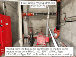
Wiring from the fire pump controllers to the fire pump motors must be in rigid metal conduit, intermediate metal conduit, electrical metallic tubing, liquidtight flexible metal conduit, liquidtight flexible nonmetallic conduit Type LFNC-B, or listed Type MC cable with an impervious covering [Sec. 695.6(D)(1)], as shown in Fig. 2.
Fittings must be listed for use in wet locations, as noted in Sec. 695.6(D)(2). The connections in the motor terminal box must be made with a listed device [Sec. 695.6(D)(3)]. Twist-on, insulation-piercing type, and soldered wire connectors are not allowed.
Ground-fault protection of equipment (GFPE) is not permitted in the fire pump power circuit [Sec. 695.6(G)]. However, you can have a GFCI convenience receptacle in the pump room for things like a vacuum cleaner, portable lights, and test equipment.
Terminations
Where raceways or cables are terminated at a fire pump controller, these requirements apply [Sec. 695.6(J)].
(1) Raceway or cable fittings must be listed and identified for use in wet locations.
(2) The type rating of the raceway or cable fittings must be at least equal to that of the fire pump controller.
(3) Follow the pump controller manufacturer’s instructions.
(4) Alterations to the fire pump controller (other than raceway or cable terminations) must be approved by the authority having jurisdiction.
Control wiring
Control wiring must be in rigid metal conduit, intermediate metal conduit, liquidtight flexible metal conduit, electrical metallic tubing, liquidtight flexible nonmetallic conduit, or Type MC cable with an impervious covering [Sec. 695.14(E)].
Equipment
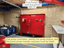
Diesel engine fire pump controllers, electric fire pump controllers, electric motors, fire pump power transfer switches, foam pump controllers, and limited-service controllers must be listed for fire pump service [Sec. 695.10], as shown in Fig. 3.
Fire pump controller and power transfer switches must be located or protected so they are not damaged by water escaping from pumps or pump connections [Sec. 695.12(E)]. Assume the worst case, and protect against it.
Beyond the NEC
Remember why the fire pump is there, and think about how to ensure it runs when you need it to. Consider adding pest control, humidity monitoring, vibration monitoring, power monitoring, security cameras, and intake screen monitoring. Don’t consider excluding it from scheduled testing and maintenance.
These materials are provided by Mike Holt Enterprises in Leesburg, Fla. To view Code training materials offered by this company, visit www.mikeholt.com/code.
