Conductor Sizes Directly Related to Terminal Temperature Ratings
Although the requirements for limiting the ampacities of conductors to that of the terminal temperature ratings found in NEC Table 310.15(B)(16) has been clear in Sec. 110.14(C)(1) for many years (since the reference to the specific table was added several Code cycles back), confusion still exists on what this Section means and how it affects conductor sizes. Let’s try and clear the air a bit by reviewing a couple of real-world examples of how to apply these Code requirements.
Example No. 1
The calculated minimum ampacity of a conductor is 200A. Type XHHW-2, 600V, copper wire is being used on the circuit. The parameters found at the top of Table 310.15(B)(16) are met in this case, so we can use the table values verbatim.
The circuit breaker is a thermal magnetic type rated 200A. The terminals on the breaker are marked 75°C. Voltage drop isn’t an issue. No. 2/0 AWG conductors are chosen with an ampacity of 195A. This is allowed in this case per Sec. 240.4(B) because we’ve met conditions (1) through (3).
So, we have 195A wire connected to a 200A breaker. On the surface, this appears to be a Code-compliant installation. However, since we’re using 90°C degree insulation, the wire is rated at 195A, but per Sec. 110.14(C)(1) we can’t exceed the ampacity of the 75°C column, which is only 175A in this case. Therefore, we have to go up in size with the conductors to a rating of at least 200A in the 75°C column. In this case, we’d have to use a minimum of No. 3/0 AWG, copper conductors.
Although in this specific example the increased size of conductors wasn’t extreme, let’s take a look at another example where there is a large impact of the terminal ratings on the minimum conductor size.
Example No. 2
The calculated minimum ampacity of a conductor is 1,000A. Type XHHW-2, 600V, copper wire is being used on this circuit. The cables will be parallel, two conductors per phase. The cables are installed in cable tray and comply with the requirements of Sec. 392.80(A)(2)(c). So, we can use the ampacity values found in Table 310.15(B)(17).
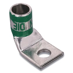
The 1,000A breaker has 90°C rated bus-type terminals on the breaker and 90°C rated compression lugs on the cable, so this termination is rated for 90°C. But, keep in mind that even though we initially thought we were allowed to use Table 310.15(B)(17), we’re limited to the ampacities of Table 310.15(B)(16) for the breaker terminals.
Using Table 310.15(B)(17) alone, it looks like we could use two, parallel, 300kcmil conductors per phase, which would give us the 1,000A of ampacity that we need. Now, we look at Table 310.15(B)(16) values for the breaker because we must follow the requirements of Sec. 110.14(C)(1). We find that to get a rating of 500A per conductor (1,000A for the combination of the two parallel conductors), we’d have to use a minimum of 700kcmil per each conductor. That’s a huge difference from the parallel 300kcmil wire that we initially thought we could use.
Lesson of the day
Always remember to keep the restrictions of the terminal temperature ratings in mind when sizing conductors. Not doing so could result in a very expensive mistake. There are very few cases where the high ampacities of Table 310.15(B)(17) can be utilized because all wire has to be terminated at some point. There are also very few instances where the 90°C column of Table 310.15(B)(16) can be used for anything other than ambient temperature adjustments or derating due to limitations of the terminals.
© 2016 Fluor Corporation. All Rights Reserved
About the Author
Eddie Guidry
Senior Fellow
Eddie Guidry is a senior fellow with Fluor Enterprises, Inc., Sugar Land, Texas. He is highly skilled in electrical and control systems for industrial construction, design, and engineering (both domestic and abroad). The majority of Eddie’s 38 years of experience includes upstream and downstream portions of petrochemical plants and refineries. He is also heavily experienced in water and wastewater treatment facilities. Eddie is very active in the development of U.S. national (ANSI) and international codes and standards, and has been a principal member of the National Fire Protection Association (NFPA) National Electrical Code (NEC) committee since 1999 and NFPA’s National Advisory Committee on Electrical Safety Research since 2008. Eddie, who has also developed and conducted many electrical courses and seminars over the years, currently holds the corporate Master Electrician license for Fluor Corporation in the State of Texas and is also an ICC/IAEI certified electrical inspector.

