
This article is part of a multi-part series on how to identify, monitor, diagnose, and deal with harmonics in electrical power systems. Last month’s column discussed how to take the data gathered when measuring harmonic levels and develop mitigation or reduction techniques for lowering total harmonic distortion (THD). This month, we will expand on the topic of mitigation techniques.
In 2017, we were asked to help a large waste-water client with commissioning a 1,492kW, 4,160V 4-pole induction motor (with VFD) and the unacceptable harmonics generated by this large medium-voltage motor. At full load, the current per phase is approximately 230A with a THD of the fundamental, plus the first 99 harmonics is 3.49% (Fig. 1).
.")

While the full load test was acceptable, the quarter load test (57A at 4,160V) produced more than twice the THD and was unacceptable per the commissioning specifications (Fig. 3). The information from the vendor indicated a maximum THD for the full bandwidth of the first 100 harmonics plus any DC instrumentation offset, and an allowance for noise will be no more than 5.0% THD.
")
- Positioning the non-linear loads (VFD, etc.) upstream in the power system (Fig. 4A).

- Grouping the non-linear (noisy) loads away from the sensitive equipment (Fig. 4B).

- Creating separate upstream power sources for linear and non-linear loads (Fig. 4C).

- Installing isolation transformers based on the harmonic frequency to be limited (Fig. 4D).

- Installing line reactors (Fig. 5). This is especially helpful for VFDs, as the current waveform can be smoothed out by increasing the line impedance of the supply circuit, limiting harmonic currents.

Specific transformer configurations can limit certain frequencies. Traditional delta-wye transformers limit 3rd harmonics (180 Hz). A delta-wye-delta configuration (Fig. 4D) can limit 5th and 7th harmonics. A delta zig-zag transformer can limit 5th harmonics.
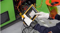
For example, a line reactor was ordered and installed for the 1,492kW, 4,160V VFD motor at the wastewater plant. Line (and load) reactors are classified by their percent impedance (denoted as percent %Z), which is the voltage drop due to impedance, at the rated current, expressed as a percent of rated voltage. The most common line reactors have either 3% or 5% impedance. Reactors with 3% impedance are usually sufficient for most solid-state applications in North America. They absorb normal line spikes and motor current surges and can prevent most nuisance line tripping of circuit protection devices. AC line reactors help reduce the level of harmonics on the electrical system by effectively expanding out and reducing the peaks caused by a VFD’s inverter (as shown in the Photo).
, can help reduce the level of harmonics on the system.")
When higher line disturbances are present, such as the situation described here, 5% impedance reactors may be needed. A higher impedance reactor is generally recommended if an application requires IEEE 519 compliance. If the aim is to diminish noise from the motor or to extend motor life, higher impedance reactors can be used to reduce harmonics even further. This additional performance typically comes at a higher cost than 3% impedance versions (due to system losses). But when multiple motors are controlled by a single drive, a single load reactor can be placed between the VFD and the motors, simplifying the system layout and reducing cost.
As shown in this case, there are options available to reduce harmonic levels in power systems on small or large applications. Next month, we will discuss a new term related to harmonics in distributed generation situations (e.g., wind, solar, etc.).
David Colombo, P.E. is a professional engineer located in Massachusetts, and the owner and principal of Power Engineers, LLC, a design, engineering, and consulting firm. He has more than 30 years in the electrical engineering and construction industry and is involved with the design of utility substation & distribution infrastructure, large-scale renewable energy projects, and commercial / industrial power systems. He specializes in the areas of medium-voltage design, power distribution, protection, metering, power quality, power studies, and arc flash analysis. He also provides owner’s engineering support for developers, EPC contractors, and project owners. Prior to starting Power Engineers, LLC and being an engineering consultant, he was a utility distribution supervising engineer. He holds a bachelor of science degree in electrical engineering from Worcester Polytechnic Institute (WPI) and a master of engineering degree in electric power engineering from Rensselaer Polytechnic Institute (RPI). He is a registered professional engineer in 13 states.


")