A facility manager reported its uninterruptible power supply (UPS) was constantly alarming on high voltage during random periods throughout the week. The voltage would occasionally reach or exceed on average 108% of nominal. There were also stretches of time — days or even weeks — where the UPS would not alarm at all, indicating this may be an intermittent problem.
The facility manger was looking for an immediate resolution. Due to the random nature of this problem, taking voltage spot reads from a multimeter would have probably been a lengthy troubleshooting option. Therefore, the power quality investigation team used a recording device with the capability of storing and trending data to help pinpoint the problem and resolve this situation.
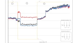
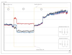
This facility was subjected to various voltage levels from an automated 3-phase capacitor bank. The data in the Figure (below) was pulled from the recording device, which was monitoring the current on the circuit feeding the UPS.
Section 1 of the Figure shows that when the capacitor is connected, the current magnitude on all three-phases is roughly the same. However, in Section 2, when the capacitor bank is commanded to disconnect, the current becomes highly unbalanced. The abnormal current imbalance prompted the team to investigate the capacitor.
In overlaying the circuit’s current data with the capacitor’s status data, the team found that one of the switches, S1, was not operating when the capacitor was signaled to turn off. The failed switch left two phases connected to the capacitor bank, while the other switch, S2, disconnected one phase. (See inset diagrams in the Figure.)
The unbalanced current caused the voltage on one of the phases to exceed the high-voltage limit on the UPS, which triggered the device’s alarm. When the capacitor was signaled to turn on, the operable switch (S2) reconnected the disengaged phase and returned the voltage and current back to its balanced state.
The failure of switch S1 to disconnect occurred every time the capacitor operated. After replacing the bad switch, the abnormal voltage levels no longer appeared on the system.


