All questions and answers are based on the 2011 NEC.
Q. Please explain the equipment temperature terminal rating for sizing conductors?
A. Conductors are to be sized using their ampacity from the insulation temperature rating column of Table 310.15(B)(16), which corresponds to the lowest temperature rating of any terminal, device, or conductor of the circuit [110.14(C)(1)]. Unless the equipment is listed and marked otherwise, conductor sizing for equipment terminations must be based on Table 310.15(B)(16) in accordance with (a) or (b) [110.14(C)(1)]:
(a) Equipment rated 100A or less must be sized using these rules:
- Conductors must be sized using the 60°C temperature column of Table 310.15(B)(16).
- Conductors terminating on terminals rated 75°C are sized in accordance with the ampacities listed in the 75°C temperature column of Table 310.15(B)(16).
- Conductors must be sized using the 75°C temperature column of Table 310.15(B)(16).
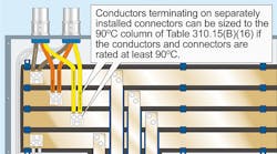
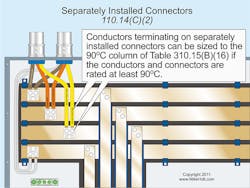
- Separate connector provisions. Conductors can be sized to the 90°C column of Table 310.15(B)(16) if the conductors and pressure connectors are rated at least 90°C, as shown in Fig. 1.
Q. Can you please explain the 10-ft feeder tap rule and provide an example?
A. Except as permitted by 240.21(A) through (H), overcurrent devices must be placed at the point where the branch circuit or feeder conductors receive their power. Taps and transformer secondary conductors aren’t permitted to supply another conductor (tapping a tap isn’t permitted) [240.21]. Branch circuit taps are permitted in accordance with 210.19 [240.21(A)]. Conductors can be tapped to a feeder as specified in 240.21(B)(1) through (B)(5). The “next-size-up protection rule” of 240.4(B) is not permitted for tap conductors [240.21(B)].
Feeder tap conductors up to 10 ft long are permitted without overcurrent protection at the tap location if the tap conductors comply with the following [240.21(B)(1)]:
-
1) The ampacity of the tap conductor must not be less than the calculated load in accordance with Art. 220 [240.21(B)(1)(1)(a)] and the rating of the device or overcurrent device supplied by the tap conductors [240.21(B)(1)(1)(b)].
2) The tap conductors must not extend beyond the equipment they supply.
3) The tap conductors are installed in a raceway if they leave the enclosure.
4) If the tap conductors leave the enclosure or vault in which the tap is made, the tap conductors must have an ampacity not less than one-tenth of the rating of the overcurrent device that protects the feeder.
Note: See 408.36 for the overcurrent protection requirements for panelboards.
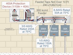
A 400A breaker protects a set of 500kcmil feeder conductors. There are three taps fed from the 500kcmil feeders that supply disconnects with 200A, 150A, and 30A overcurrent devices. What are the minimum size conductors for these taps (see Fig. 2)?
- 200A: 3/0 AWG is rated 200A at 75° and is greater than 10% of the 400A overcurrent protection device (40A).
- 150A: 1/0 AWG is rated 150A at 75° and is greater than 10% of the 400A overcurrent protection device (40A).
- 30A: 8 AWG is rated 50A at 75° and is greater than 10% of the ampacity of the 400A overcurrent protection device (40A).
Anything smaller than 8 AWG can’t be used, as it will have an ampacity of less than 10% of 400A (40A) in the 75° column of 310.15(B)(16).
Q. Does the Code allow metal cable tray systems to be installed in spaces used for environmental air (plenum)?
A. Yes, metal cable tray systems can be installed to support the wiring methods and equipment that are permitted to be installed in this location [300.22(C)(2)(a)].
Q. What are the minimum bending radius requirements for Type NM and Type MC Cable?
A. Bends in MC Cable must be made so that the cable won’t be damaged, and the radius of the curve of any bend at the inner edge of the cable must not be less than what’s described in each of the following instances:
- Smooth-sheath Type MC cables must not be bent so the bending radius of the inner edge of the cable is less than 10 times the external diameter of the metallic sheath for cable up to ¾ in. in external diameter [330.24(A)(1)].
- Interlocked- or corrugated-sheath Type MC cable must not be bent so the bending radius of the inner edge of the cable is less than seven times the external diameter of the cable [330.24(B)].
When Type NM Cable is bent, it must not be damaged and the radius of the curve of the inner edge of any bend must not be less than five times the diameter of the cable [334.24].
Q. What is the rule on having a neutral conductor at light switch locations?
A. Switches controlling line-to-neutral lighting loads must have a neutral provided at the switch location [404.2(C)].
Ex: The neutral conductor isn’t required at the switch location if:
-
1) The conductors for switches enter the device box through a raceway that has sufficient cross-sectional area to accommodate a neutral conductor.
2) Cable assemblies for switches enter the box through a framing cavity that’s open at the top or bottom on the same floor level, or switches enter the box through a wall, floor, or ceiling that’s unfinished on one side. Note: The neutral conductor’s purpose is to complete a circuit path for electronic lighting control devices.
