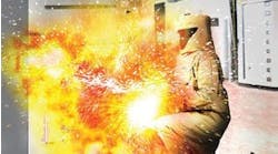
The tell-tale sound, flash of light, flames, and resulting smoke is the ultimate workplace nightmare: an arc flash incident. Something has gone wrong, and people and equipment are in danger. In simplest terms, an arc flash or arc fault occurs when electricity leaves its intended path and travels from one conductor to another or to ground (Photo 1). An arc flash can generate an electric arc with a temperature of 35,000°F, approximately four times the temperature of the sun’s surface. Equipment can start breaking up when an event exceeds 15 cal/cm2. The severity of an arc flash event is directly related to the available incident energy and the duration of the event.

There are many causes of arc flash events. Often, they are driven by human error: the use of uninsulated tools during energized work, accidental contact with exposed live parts, and using damaged equipment. Some arc flash incidents are a direct result of the condition of the equipment, such as a loose connection, water intrusion, or worn/damaged insulation (Photo 2 and Photo 3). These items can often be identified during normal inspections — when, and if, they are performed.


Maintenance, inspections, and testing
Environmental factors are another issue that can plague mechanical devices (Photo 4). Contaminants, moisture, extreme temperatures (both hot and cold), and the atmosphere that the breaker operates in can all add to operational issues for a circuit breaker. Sometimes, these are obvious during an inspection, like a breaker covered in coal dust or current-carrying components that are blackened and damaged by hydrogen sulfide in a wastewater treatment plant. Environmental damage might be harder to spot, however. Rusted bearings deep within a mechanism or damaged contacts inside switches or relays may not be visible but can hinder the correct tripping of a breaker. Operational cycles on a circuit breaker are another consideration. A breaker that is used as a motor starter may have incurred enough operations to have worn mechanism components, internal parts, contacts, or weakened springs, making the device less effective at doing its job.

Incident energy considerations
What happens when a breaker doesn’t trip as expected, only partially opens, or doesn’t trip at all? In all scenarios, available incident energy increases as the clearing time increases. This increase in available incident energy results in hazards to both personnel and equipment. Partial tripping can be extremely hazardous, especially in medium-voltage applications; the partial contact gap may not be sufficient to break the circuit and may generate conductive ionized air. In addition to a fault, delayed or nonexistent tripping can cause that fault to be cleared by an upstream device, resulting in an outage that affects multiple circuits instead of just one.
Qualified personnel are trained to use all information available to assess the risk when racking or operating a circuit breaker. The first step is often to review the arc flash label for that particular device. An arc flash label indicating the potential hazard doesn’t necessarily keep people completely safe from electrical dangers. However, the label provides a calculated arc flash hazard as well as arc flash boundary distance. These values are based on the premises that the equipment was properly installed/maintained, all doors and covers are closed and secured, and there are no signs of impending failure (Photo 5).

Let’s look at the same breaker under two different scenarios. Table 1 shows the arc flash label calculations for a breaker that meets all of the requirements above. This particular breaker has a short-circuit function that is set so that an 8.11kA fault is interrupted in 0.143 seconds. Under these conditions, this breaker has an incident energy of 2.13 cal/cm2 and an arc flash boundary of 22 inches. These values should allow for operation of the equipment with basic personal protective equipment (PPE) and a relatively low hazard to operators.

If the same breaker is in poor condition, has not been maintained, or the maintenance information is not known, the assumption of correct operation cannot be made. This same breaker that has the trip time increased to just 2 seconds from 0.143 seconds now has arc flash boundary and incident energy numbers that increase dramatically (see Table 2). The increase in fault clearing time extends the arc flash boundary to 112 inches and increases the incident energy to 29.70 cal/cm2.

In the first scenario, since the incident energy displayed on the arc flash label is calculated at 2.13 cal/cm2, an operator would likely select Category 1 or Category 2 PPE with a minimum arc rating of 4 cal/cm2 or 8 cal/cm2. When that same breaker fails to trip as expected — and there is an arc flash event — the operator is now in an extremely dangerous situation and is not equipped with the proper PPE to avoid injury. The resulting increase in incident energy would now require the operator to wear Category 4 PPE, which is designed for use up to 40 cal/cm2. It is important to remember no matter what the Category rating, that PPE is designed to protect workers from non-recoverable injuries — not from walking away unscathed. The calculated ratings of PPE are set to prevent anything worse than a 2nd degree burn and to provide some shielding from flying debris. In the second scenario, the operator is woefully underdressed and could be exposed to life-threatening hazards. When racking or operating electrical equipment, it is usually not assumed that a fault will occur, but approaching these tasks in a proactive manner will go a long way toward protecting personnel.
2018 IEEE 1584 calculations
There is additional information to consider when evaluating values listed on arc flash labels. In 2018, the IEEE 1584 formulas for calculating arc flash hazards were revised. The NFPA evaluated data collected over several years and determined that the formulas should be revised and enhanced to better reflect the actual hazards to personnel. Prior to 2018, one formulaic constant was used to represent the size of all cabinets. In addition, neither the orientation of conductors nor the location of the circuit — in an enclosure or in open air — were considered. The new formulas now take all of these parameters into account.
While NFPA 70E Sec. 130.5(G) requires any existing study to be reviewed for changes every five years and updated accordingly, the standard does not require recalculation if no changes have been made. There is not a requirement to replace labels because of the 2018 formulaic changes. There are many labels in use that were generated prior to 2018 that do not utilize these new formulas. This poses additional hazards for qualified workers. The original cubicle size calculation constant was based on a 20-inch × 20-inch × 20-inch compartment. The calculation change has the most impact on devices in shallow cabinets. With less volume available, any incident in a shallow cabinet — often only 8 inches or 12 inches deep in a motor control center bucket or panel — will most likely have a higher incident energy hazard than indicated on an older label. It is important to carefully evaluate the equipment that is scheduled for operation with this added factor in mind.
Hazard risk assessment
It is important to recognize that there are many factors that must be considered when planning for electrical racking and switching tasks. Evaluating the information on an arc flash & shock hazard label is just the beginning. The need for regular operation, inspection, and maintenance of equipment greatly impacts the accuracy of that information. Careful evaluation of these components is a crucial part of the pre-task hazard risk assessment. This was recognized as an essential component to electrical workplace safety by the NFPA and is now a requirement in the 2023 NFPA 70B instead of a suggested practice. This change in language, along with refinements to the engineering calculations for arc flash hazard labels, is a positive step to increased worker safety and to the reduction in equipment damage because of arc flash incidents.
Denise Green is the Midwest regional sales manager and national breaker specialist for Group CBS and has been in the electrical distribution industry for 33 years. She can be reached at [email protected].
This article was provided by the InterNational Electrical Testing Association (NETA), www.NETAworld.org. NETA was formed in 1972 to establish uniform testing procedures for electrical equipment and systems. Today the association accredits electrical testing companies; certifies electrical testing technicians; publishes the ANSI/NETA Standards for Acceptance Testing, Maintenance Testing, Commissioning, and the Certification of Electrical Test Technicians; and provides training through its annual PowerTest Conference and library of educational resources.