Insulation failure is the root cause of many electrical conductors and equipment failures. When insulation fails, not only can equipment be damaged, but fire and shock can also result. Ideally, when the current leaves its normal path through a conductor, proper bonding will result in the overcurrent device clearing the fault. Being able to predict insulation failure is a great advantage of preventive maintenance technologies. In addition to safety, every maintenance contractor and organization must have goals to reduce replacement/repair costs and downtime. Measuring insulation resistance properly and correct interpretation of those measurements plays a large part in meeting these goals.
Understanding insulation resistance measurements
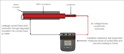
The analogy of equating water flow through a piping system to measuring the quality of electrical insulation works well. For example, upon completion of installing a new piping system, it would only make sense to perform a leak test — and do so at a higher pressure than the normal operating pressure. Routine maintenance may also require testing as the system ages. Electrical insulation breaks down over time. The heating and cooling of the insulation, equipment vibration, and contaminants that enter the equipment all combine to degrade the insulation quality over time. The result is that electrical current unintentionally leaks into non-current-carrying conductors, metal enclosures, metal raceways, metal equipment, or earth (see Fig. 1). This is the National Electrical Code’s definition of a “ground fault.”
Ground faults are undesirable. Not only is insulation degradation over time a culprit, but ground faults can also occur during installation work. Insulation can be scraped from a conductor as it is pulled through a conduit. A conductor can be pinched between a cover and its enclosure. Always verify a system is clear of ground faults prior to initially energizing the system. Insulation quality testing during acceptance and commissioning can identify problems that would prevent the proper functioning of equipment and systems. Measuring and evaluating the quality of electrical insulation increases safety and reduces unexpected downtime — a win-win situation.
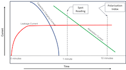
When applying DC voltage to a conductor, three separate currents flow. Just like charging a capacitor, some current flows to create a capacitive charge between the conductor under test and nearby conductors and from the conductor to ground. These are known as capacitive charging currents. Current flows also polarize any moisture or contamination molecules in the insulation. This is called absorption current. Finally, some current that is flowing is leaking from the conductor through the insulation into either the non-current carrying metal components of the system or into another conductor with poor-quality insulation. This is called leakage current. Fortunately, by applying the DC test voltage, the capacitive and the absorption currents will tend to read zero after a short time, and the remaining current flowing out of the conductor through the insulation is primarily leakage current.
These current values are indicated on the insulation resistance test equipment in ohms (see Fig. 2). Typically, the actual values will be in millions of ohms (Ω). 1MΩ = 1,000,000 ohms. Modern testers can measure gigaohms of resistance. 1 GΩ = 1,000,000,000 ohms. A reading in kilohms (1 kΩ = 1,000 ohms) is generally an indication of a severe insulation problem.
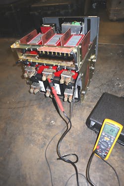
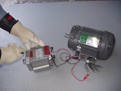
An insulation resistance tester or megohmmeter is the most common type of test equipment used to measure insulation resistance (see Photos 1a and 1b). Like the pump for a leak test on a piping system providing high pressure, the megohmmeter forces current flow through a conductor using a voltage greater than for what the insulation is rated. For example, 600V-rated insulation may be tested at 1,000VDC. A common error in the field is to use a digital multimeter (DMM) to attempt to measure insulation resistance. The DMM only produces a very small voltage; it is not enough to detect a breakdown in insulation. More sophisticated tests (especially for medium- and high-voltage cables/equipment) may use AC or a very low frequency (VLF) AC for testing.
For the type of test to be conducted and the interpretation of results, always use the manufacturer’s instructions. IEEE 43, Recommended Practice for Testing Insulation Resistance of Rotating Machinery, provides widely used industry values for test voltages and satisfactory test results.
Performing the insulation resistance test
Rule No. 1: “De-energize all equipment and conductors under test prior to beginning any test.” In other words, use an electrical lockout/tagout procedure to create an electrically safe work condition. Part of that procedure requires removing any stored energy as well. Longer cable runs and motors can store significant amounts of electrical energy. Many insulation resistance testers are designed to discharge these currents before and after testing. If this function is not available on the tester used for measurements, a static discharge stick with built-in resistance should be used for discharging circuits before and after tests.
Once this safe condition is properly verified, the test process can begin. Follow the manufacturer’s instructions to set up the test set. Insulation quality is measured from each ungrounded conductor to ground and between individual ungrounded conductors. The part of the system under test must also be disconnected from other parts to ensure no parallel paths to ground exist, which would give an erroneous reading.
The area under test is barricaded to prevent electric shock to an unqualified person. Follow the rules of shock protection found in NFPA 70E, Standard for Electrical Safety in the Workplace. The black test lead connects to ground — bare metal or the ground connection on the equipment. The red test lead connects to the bare ungrounded conductor. Insulation resistance will change with temperature changes. For consistency of readings over time, insulation temperature is measured, and charts are used to correct readings to a standard 40°C.
The appropriate test voltage is applied, and current begins to flow into the conductor material. Almost immediately, leakage current flows and will remain constant throughout the test. Just as current is used to charge a capacitor, some current is also flowing into the conductor to create the capacitive charge between the conductor and ground and between adjacent conductors. Any readings taken during the charging time of this capacitive charging process will result in an inaccurate leakage current reading. The capacitive current should be at or near zero after one minute. Taking a reading at one minute is referred to as a “spot-reading” test. It is the typical value used for determining insulation quality for many types of equipment.
In addition to leakage current, the absorption current continues to flow beyond the one-minute mark. As the impurities in the insulation are polarized, the absorption current drops to or at near zero. An increasing resistance value as the test proceeds toward 10 minutes is an indication of contamination on or in the insulation. The polarization index (PI) is the ratio obtained when dividing the 10-minute reading by the one-minute reading. A low ratio indicates questionable insulation quality.
Another method to determine insulation resistance quality is to divide the one-minute reading by a 30-second reading. This test is the dielectric absorption ratio (DAR). Follow the manufacturer’s instructions, or refer to the IEEE 43 standard for specific values.
Applications
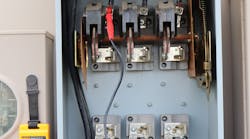
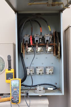
Insulation resistance quality should be verified when electrical systems and equipment are installed as part of acceptance testing and commissioning of facilities. For example, nicked insulation in a conduit or pinched wires in an enclosure covering can be found. Identifying ground faults or short circuits between conductors is critical to startup. Section 110.7 of the NEC prohibits ground faults (see Photo 2). Measuring electrical insulation quality can be used during troubleshooting to identify faulty insulation as the cause for blowing fuses or tripping circuit breakers. NFPA 70E requires the cause of a blown fuse or tripped circuit breaker to be determined prior to replacing the fuse or resetting/closing the circuit breaker.
A major advantage of periodically measuring insulation resistance is that the degradation of the insulation can be plotted over time — typically in months and years. Plotting out resistance values as they decrease can be used to help predict the failure of electrical systems and equipment. Repairs can be scheduled and made prior to more costly unscheduled downtime. By performing a polarization index test, damp or contaminated insulation can be corrected. Procedures exist to dry out windings in motors and generators. Windings can be cleaned using different methods, often significantly raising insulation resistance values.
Increasing personnel safety, preventing fires, and reducing downtime are goals of all organizations and electrical workers. Part of reaching those goals requires measuring the insulation quality of electrical systems and their components as part of installation, troubleshooting, and routine maintenance. Understanding the basics, following manufacturer instructions and industry standards for proper test methods, and interpreting measurements correctly to determine insulation quality provides for a safe and efficient work environment.
Randy Barnett is the electrical codes and safety program manager for NTT Training in Centennial, Colo. A certified electrical safety compliance professional (CESCP), he can be reached at [email protected].
SIDEBAR: Use Ohm’s Law to Understand Insulation Resistance Testing
Ohm’s Law explains how insulation resistance is measured. Understanding this simple formula helps to interpret readings.
From Ohm’s Law:
R = E ÷ I, where (R) is resistance in ohms, (E) is voltage in volts, and (I) is current in amperes.
If the current increases the resistance will decrease:
- Low leakage current would result in a higher resistance value (desired).
- Increased leakage current results in a lower resistance value (undesirable).
Motor insulation resistance example:
1,000VDC is applied to a motor winding. Using R = E ÷ I and given the below leakage currents through the winding insulation into the frame of the motor, what is the insulation resistance reading?
If 0.00004A flows through the winding insulation into the frame of the motor, the megohmmeter would read 25 megohm (MΩ), a satisfactory reading to safely operate the motor.
25 MΩ = 1,000VDC ÷ 0.00004A
If 0.001A flows through the winding insulation into the frame of the motor, the megohmmeter would read 1 megohm (MΩ), which is generally an unsatisfactory value. Running this motor may result in total motor failure requiring rewinding or replacement.
1 MΩ = 1,000VDC ÷ 0.001A
