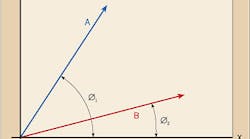
What is a vector, and how can we use it in electrical design? According to the “IEEE Standard Dictionary of Electrical and Electronic Terms,” a vector quantity is “any physical quantity whose specification involves both magnitude and direction and that obeys the parallelogram law of addition.” This may sound confusing, so we're going to clarify this definition in Part 1 of this article. In Part 2, we'll show how you can use vectors and vector analysis in electrical design to determine the following:
Impedance in complex circuits containing inductance,
Required kvar to attain a specific power factor, and
Vectors
Phase and neutral currents on both balanced and unbalanced 3-phase circuits.
Right now, let's start by clarifying that confusing definition.
A vector quantity is represented by a line having magnitude and direction. The relative length of the line represents the vector's magnitude, while the line's position (angle from the X-axis) and arrowhead represent the vector's direction (Fig. 1). Common vector quantities include acceleration, force, velocity, and alternating currents and voltages. By comparison, quantities such as inches and feet are called scalar quantities and have magnitudes only.
Vectors are usually indicated by boldface type (A) or by an arrow or bar over the symbol. In our discussion here, we'll use the boldface type designation.
To add two vectors, say A and B, you would place B at the end of A. Note that both A and B must maintain their respective magnitude and direction. The result of this addition will be C, as shown in Fig. 2. Note that it has a different magnitude (length) and direction (position). Also note that the magnitude and direction of C is governed by Point P (on the X/Y axis), whose X-axis coordinate is X1 plus X2 and whose Y-axis coordinate is Y1 plus Y2.
Finally, note that if we draw a dotted line from the 0-point of the X/Y axis (parallel to and of the same length as B) and another dotted line from here (parallel to and of the same length as A), the magnitude and direction of C would be the largest diagonal. In fact, the figure comprised of A, B, and the two dotted lines is a parallelogram, which is a four-sided figure in which opposite sides are of equal length and parallel. Now you understand the “parallelogram law of addition” reference in the IEEE definition of a vector.
To subtract B from A, you would place B at the beginning of A. Again, both vectors must maintain their same magnitudes and directions. Now, the magnitude and direction of C is governed by Point Q, whose X-axis coordinate is X1 minus X2 and whose Y-axis coordinate is Y1 minus Y2. The result will be C, as shown in Fig. 3, again having a different magnitude and direction than A or B. Note that a parallelogram is formed by joining the end points of A, B, and C.
Basic laws. There are certain basic laws you must know when working with vectors. Let's take a look at them.
- Equality
A = B if and only if both vectors have the same magnitude and direction.
- Addition and subtraction
The commutative law states that A + B = B + A. The associative law states that A + B + C = (A + B) + C = A + (B + C). You can easily prove this by making the graphical additions and subtractions using the procedures previously noted.
- Product of a scalar times a vector
A scalar (s) times a vector A equals sA, which is also equal to As.
- Multiplication of two vectors
Let's look at Fig. 4. Multiplying A times B will result in C, whose magnitude equals the magnitude of A times the magnitude of B, and whose angle (Ø) from the X-axis equals Ø1 plus Ø2.
- Division of two vectors
Let's look at Fig. 5. Dividing A by B results in C, whose magnitude is equal to the magnitude of A divided by the magnitude of B, and whose angle (Ø) from the X-axis equals Ø1 minus Ø2.


