Among the revisions to Art. 250, the 2014 NEC made some important wording changes that clear up confusion. For example, the NEC previously used the terms “service laterals” and “service drops.” But these aren’t the only two ways electricity can get to an electric utility-supplied building [250.24]. The 2014 NEC uses more inclusive language to reflect the real world. Several other instances of word changes in the 2014 NEC improve Art. 250.
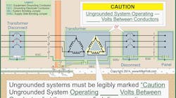
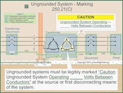
Other changes are more prescriptive. For example, the signage requirement for ungrounded systems of 50V to 1,000V now requires more useful information. The 2011 NEC added a requirement for marking ungrounded systems. The idea was to alert electricians that they were dealing with an uncommon system. Although that change helped make the workplace safer, it would be even better to actually indicate the voltage. Now, installers must mark the voltage of the ungrounded system. The requirements [250.21(C)] are similar to the requirements for a high-leg system [408.3(F)], as shown in Fig. 1.
Grounding electrode conductor
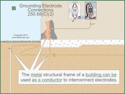
The 2011 NEC added new text [250.68(C)] that had the unintended consequence of permitting installers to use interior water pipe and structural metal as GECs. Now, the NEC says GECs must be copper, aluminum, or copper-clad aluminum or the items permitted in 250.68(C) [250.62]. Section 250.68(C) allows the interior metal water pipe and the metal structure of a building to be used as a conductor to “interconnect” electrodes. Because buildings are typically not built of copper, using the metal structure as a conductor was a small conflict between 250.62 and 250.68(C), as shown in Fig. 2. The changes to these sections resolved a conflict that only the keenest of Code-reading eyes even noticed.
The way you install a GEC must conform to 250.64(A) through (F). We’ll take a quick look at B and E (which cover conductor protection), then a closer look at D (which covers multiple disconnects).
Conductor protection
You must protect exposed GECs where subject to physical damage. You can install them on (or through) framing members [250.64(B)]. You can install GECs 6 AWG copper and larger exposed along the surface of the building if you fasten them securely and they aren’t subject to physical damage.
It may save you money to size all your GECs 6 AWG or larger. Why? You must protect GECs sized 8 AWG copper or
6 AWG aluminum (smallest sizes permitted [Table 250.66]) by installing them in rigid metal conduit, intermediate metal conduit, PVC conduit, electrical metallic tubing, or reinforced thermosetting resin conduit.
Multiple disconnects
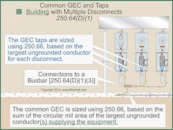
If a service or structure disconnect consists of more than a single enclosure, grounding electrode connections must be made in one of the following methods [250.64(D)]:
• Common GEC and taps.
• Individual GECs.
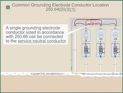
• Common location.
Let’s examine these.
A GEC tap must extend to the inside of each disconnecting means enclosure. Size each GEC tap per 250.66, based on the largest ungrounded conductor supplying the individual enclosure (see Fig. 4). The common GEC is also sized no smaller than specified in Table 250.66. The difference is the size is based on the sum of the circular mil area of the largest ungrounded conductor(s) of each set of conductors that supply the disconnecting means.
1) Exothermic welding.
2) Connectors listed as grounding and bonding equipment.
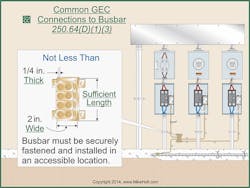
3) Connections to a bus bar of sufficient length and not less than ¼ in. thick × 2 in. wide that’s securely fastened and installed in an accessible location [250.64(F)(3)]. With the 2014 NEC, there’s a crucial change here (see Sidebar 1 below).
An individual GEC, sized per 250.66 based on the ungrounded conductor(s) supplying the individual disconnecting means, must be connected between the grounding electrode system and one or more of the following:
1) Service neutral conductor,
2) Equipment grounding conductor of the feeder circuit,
3) Supply-side bonding jumper.
You can run a single GEC from a common location (Fig. 5). But size it no smaller than specified in Table 250.66, based on the area of the ungrounded conductor where the connection is made. The GEC must connect the grounding electrode system to one or more of the following:
1) Service neutral conductor.
2) Equipment grounding conductor of the feeder circuit.
3) Supply-side bonding jumper.
Sizing GECs
The NEC has long allowed installing smaller GECs for ground rods and concrete-encased electrodes. Unfortunately, there was a subtle omission prior to the 2014 NEC. If a person can use 6 AWG to one ground rod, why not allow it for two ground rods in parallel? Installers did this, and inspectors allowed it.
The 2014 NEC corrects this omission. Except as permitted in 250.66(A), (B), and (C), you must size the GEC per Table 250.66 [250.66]. If the GEC connects to one or more ground rods as permitted in 250.52(A)(5), that portion of the GEC that is the sole connection to the ground rods doesn’t need to be larger than 6 AWG copper.
If the GEC connects to one or more concrete-encased electrodes, the portion of the GEC that’s the sole connection to the concrete-encased electrodes doesn’t need to be larger than 4 AWG copper.
Use Table 250.66 to size the GEC when the conditions of 250.66(A), (B), or (C) don’t apply.
Termination to the grounding electrode
GECs and grounding electrode bonding jumpers can terminate to [250.68]:
• The metal frame of a building/structure.
• Interior metal water piping located not more than 5 ft from the point of entry to the structure.
In commercial, industrial, and institutional buildings where conditions of maintenance and supervision ensure only qualified persons service the installation, the 5-ft rule doesn’t apply. In these cases, you can use the entire length of the metal water piping system for grounding purposes if the entire length (other than short sections passing through walls, floors, or ceilings) is exposed.
This section isn’t telling us when structural metal or water pipe is an electrode (that’s handled in Sec. 250.52). This section is simply telling us when we can use these items as conductors to connect other items together. The structural metal of a building may or may not be a grounding electrode, but it’s certainly conductive so you can use it to connect different electrodes together.
Grounding isn’t bonding
We’ve gone over some key points of grounding requirements, none of which solve problems with touch potential or prevent flashover. For that, you need bonding, which we’ll discuss in Part 2.
Holt is the owner of Mike Holt Enterprises, Inc. in Leesburg, Fla. He can be reached at www.mikeholt.com.
Sidebar 1: Bus Bar Dimensions
Sidebar 2: Don't Choke Up
Failing to bond a GEC-containing ferrous raceway at each end will significantly reduce the effectiveness of the grounding electrode. Why? Because a single conductor carrying high-frequency induced lightning current in a ferrous raceway causes the raceway to act as an inductor. Because the conductor is inside the inductor, you have physically constructed an inductive choke.
This arrangement severely limits (chokes) current flow through the GEC. ANSI/IEEE 142—Recommended Practice for Grounding of Industrial and Commercial Power Systems (Green Book) — states, “An inductive choke can reduce the current flow by 97%.”
You can bond by one of the methods discussed in 250.92(B)(2) through (B)(4). Key points include:
• Bonding jumpers must be at least the required size of the GEC in the raceway or other enclosure.
• A raceway used for a GEC must meet all of the requirements for the raceway, such as securing and supporting, number of bends, and conductor fill.
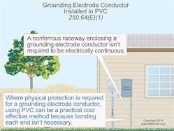
• Nonferrous metal raceways (e.g., aluminum rigid metal conduit) enclosing the GEC don’t have to meet the “bonding each end of the raceway to the grounding electrode conductor” requirement.
