It’s important to understand the difference between grounding and bonding so you correctly apply the provisions of Art. 250. We earth ground systems to the earth to reduce overvoltage (from lightning-induced energy and other events) on the conductors and electrical components (such as transformer and motor windings) of the installation. Grounding metal parts helps drain off static electricity charges before flashover potential is reached. Static grounding is often used in areas where the discharge (arcing) of the voltage buildup (static) can cause dangerous or undesirable conditions.
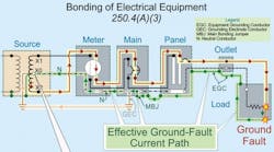
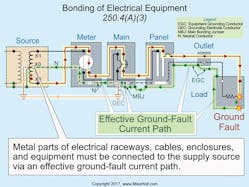
We bond so that metal parts of electrical raceways, cables, enclosures, and equipment are connected to the supply source via an effective ground-fault current path (Fig. 1). To quickly remove dangerous voltage on metal parts from a ground fault, the effective ground-fault current path must have sufficiently low impedance to the source so fault current will quickly rise to a level that will open the circuit overcurrent protection device.
System grounding
Systems operating below 50V aren’t required to be grounded or bonded per Sec. 250.30 unless the transformer’s primary supply is from a 277V or 480V system or an ungrounded system [250.20(A)].
Systems over 50V are a different story. The following systems must be grounded (connected to the earth) if the neutral conductor is used as a circuit conductor:
(1) Single-phase systems.
(2) 3-phase, wye-connected systems.
(3) 3-phase, high-leg delta-connected systems.
Ungrounded systems must:
- Have ground detectors installed as close as practicable to where the system receives its supply [250.21(B)].
- Be legibly marked “Caution Ungrounded System Operating—_____ Volts Between Conductors” at the source or first disconnect of the system, with sufficient durability to withstand the environment involved [250.21(C)].
Service equipment, grounded systems
A grounding electrode conductor (GEC) must connect the service neutral conductor to the grounding electrode at any accessible location, from the load end of the overhead service conductors, service drop, underground service conductors, or service lateral, up to and including the service disconnect [250.24(A)].
When the service neutral conductor is connected to the service disconnect [250.24(B)] by a wire or bus bar [250.28], the GEC can terminate to either the neutral terminal or the equipment grounding terminal within the service disconnect.
You can’t have a neutral-to-case connection on the load side of service equipment, except as permitted by 250.142(B).
A main bonding jumper [250.28] is required to connect the neutral conductor to the equipment grounding conductor (EGC) within the service disconnect [250.24(B)].
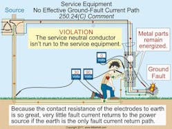
A service neutral conductor must be run from the electric utility power supply with the ungrounded conductors and terminate to the service disconnect neutral terminal [250.24(C)]. A main bonding jumper [250.24(B)] must be installed between the service neutral terminal and the service disconnect enclosure [250.28].
Dangerous voltage from a ground fault won’t be removed from metal parts, metal piping, and structural steel if the service disconnect enclosure isn’t connected to the service neutral conductor. This is because the contact resistance of a grounding electrode to the earth is so great that insufficient fault current returns to the power supply if the earth is the only fault current return path to open the circuit overcurrent protection device (Fig. 2).
Neutral sizing
The 2017 NEC brought clarification that the sizing requirements for service neutral conductors apply to cable-type wiring methods.
Try to visualize the electric utility neutral conductor as a white wire with green stripes on it. That’s really what it is; the service neutral wire carries the unbalanced return (white) and it’s the fault-clearing conductor on the supply side of the service (green stripe).
Because the service neutral conductor serves the role of carrying unbalanced current and is intended to provide a low-impedance fault return path to the electric utility secondary winding, it must be sized to carry the neutral load and the fault current back to the source in the event of a ground fault.
If we have a 400A 3-phase service supplying only 3-phase motors and one 20A line-to-neutral lighting circuit, what size neutral wire do we need?
A 12 AWG conductor will certainly carry the lighting circuit neutral load, but what about the fault current? Have you ever seen a 500kcmil phase conductor collide with a 12 AWG equipment grounding conductor? If not, you can guess that there wouldn’t be anything left of the 12 AWG conductor, other than copper vapor floating around in the air.
To ensure a safe installation, the Code requires the service neutral conductor to be sized per Table 250.102(C)(1). In our 500kcmil example, this would be a 1/0 AWG copper neutral. That kind of mass can carry the fault carry current without any problem.
Since none of this is actually new to the NEC, what changed? The 2014 Code was clear when it came to sizing the neutral conductor in a raceway, but it was dead silent when it came to sizing the neutral conductor in a cable assembly. It’s now clear that the service neutral conductor must be sized per Sec. 250.24(C) and Sec. 250.102(C)(1), whether the installation is a raceway or a cable.
Main and system bonding jumpers
At service equipment, a main bonding jumper must be installed to electrically connect the neutral conductor to the service disconnect enclosure [250.24(B)].
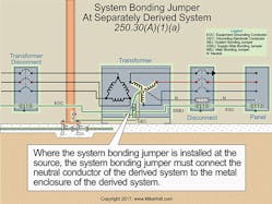
A system bonding jumper must be installed between the neutral terminal of a separately derived system and the circuit EGC [Art. 100 Bonding Jumper, System and Sec. 250.30(A)(1)] (Fig. 3).
The bonding jumper can be a wire, bus, or screw [250.28]. If the bonding jumper is a screw, it must be identified with a green finish visible with the screw installed.
Main and system bonding jumpers must terminate by any of the following means in accordance with 250.8(A):
- Listed pressure connectors
- Terminal bars
- Pressure connectors listed as grounding and bonding equipment
- Exothermic welding
- Machine screw-type fasteners that engage not less than two threads or are secured with a nut
- Thread-forming machine screws that engage not less than two threads in the enclosure
- Connections that are part of a listed assembly
- Other listed means.
Main and system bonding jumpers must be sized not smaller than the sizes shown in Table 250.102(C)(1).
Separately derived systems
The grounding and bonding requirements for separately derived systems are in Sec. 250.30. What has changed here with the 2017 NEC?
The requirement to use either structural metal or water piping as the preferred grounding electrodes was removed. Metal water piping can now be used for multiple separately derived systems, and the dimensions of the bus bar used to splice GECs were clarified.
The past few Code cycles have seen many revisions to Sec. 250.30 and
Sec. 250.68 in an effort to clarify what items can and can’t be called a grounding electrode. These revisions have had varying amounts of success. This cycle includes a change that definitely makes things easier.
- Grounding electrode. When grounding a separately derived system, we must connect the neutral point to the building’s grounding electrode system. Previous editions of the NEC said the separately derived system had to be connected to the structural metal or water pipe, and if those weren’t present, we could then seek other types of electrodes. Now in 2017, the Code simply requires us to connect the separately derived system to the building’s grounding electrode system.
- Multiple separately derived systems. When grounding multiple separately derived systems, we’ve had the option of terminating grounding electrode taps to a common 3/0 AWG copper GEC or to structural metal [250.30(A)(6)]. Why shouldn’t we be allowed to terminate to interior metal water piping? Now we can.
- Bus bar terminations. The dimensions of the bus bar that can be used to splice the common GEC and the taps have been clarified. The bus bar must be ¼ in. thick by 2 in. wide, and whatever length is necessary to accommodate the terminations.
Generators aren’t always separately derived. The requirements for portable and vehicle-mounted generators [250.34] differ from the requirements for permanently installed generators [250.35]. A generator whose transfer switch does not switch the neutral conductor is not a separately derived system, because there is a direct electrical connection between the generator and supply conductors via the unswitched neutral conductor.
Different purposes
To correctly apply the provisions of Art. 250, keep the different purposes of grounding and bonding in mind. Grounding provides a path to the earth to reduce overvoltage from events such as lightning. Bonding provides for a low-impedance fault current path back to the source of the electrical supply to facilitate the operation of overcurrent protection devices in the event of a ground fault.
These materials are provided to us by Mike Holt Enterprises in Leesburg, Fla. To view Code training materials offered by this company, visit www.mikeholt.com/code
