The NEC permits photovoltaic (PV) systems to supply power to buildings, structures, or other electrical supply system(s). PV systems can be installed on or in a single structure.
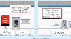
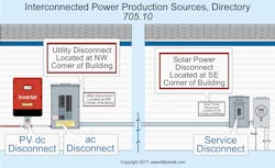
Where multiple power production sources capable of being interconnected are remote from each other, a permanent plaque or directory must be installed per Sec. 705.10. It must denote the location of all electric power source disconnecting means at the disconnecting means location for service equipment and PV system disconnecting means. The plaque or directory must be permanently affixed and have sufficient durability to withstand the environment involved [Sec. 110.21(B)] (Fig. 1).
Maximums
The maximum PV system circuit voltage is equal to the sum of the PV module rated open-circuit voltage (Voc) of the series-connected modules as corrected for the lowest expected ambient temperature using either the [Sec. 690.7(A)]:
• Manufacturer’s voltage temperature coefficient.
• Correction factor provided in Table 690.7(A).
You can calculate the maximum PV circuit current by one of the six methods listed in Sec. 690.8. Here are four of them:
1) The sum of parallel-connected PV module-rated short-circuit currents multiplied by 125% [Sec. 690.8(A)(1)(1)].
2) The maximum inverter output circuit current is equal to the maximum continuous inverter output current [Sec. 690.8(A)(1)(3)].
3) The maximum current is the standalone continuous inverter input current rating when the inverter is producing rated power at the lowest input voltage [Sec. 690.8(A)(1)(4)].
4) The maximum output current for a DC-to-DC converter is equal to its continuous output current rating [Sec. 690.8(A)(1)(5)].
Conductor Sizing
You must size PV source circuit conductors, PV output circuit conductors, and PV inverter output circuit conductors so they have an ampacity the larger of Sec. 690.8(B)(1) or Sec. 690.8(B)(2).
(1) 125% of the current as determined by Sec. 690.8(A) before the application of conductor ampacity correction [Sec. 310.15(B)(2)(a)] and ampacity adjustment [Sec. 310.15(B)(3)(a)].
(2) 100% of the current as determined by Sec. 690.8(A) after the application of conductor ampacity correction [Sec. 310.15(B)(2)(a)] and ampacity adjustment [Sec. 310.15(B)(3)(a)].
For a PV power source that has multiple output circuit voltages and employs a common-return conductor, the ampacity of the common-return conductor must be at least the sum of the ampere ratings of the overcurrent protection devices (OCPDs) of the individual output circuits [Sec. 690.8(C)].
Where a single OCPD protects a set of two or more parallel-connected module circuits, the ampacity of each of the module interconnection conductors must be at least the sum of the rating of the single OCPD plus 125% of the short-circuit current from the other parallel-connected modules [Sec. 690.8(D)].
Overcurrent Protection
PV circuit conductors, inverter output circuit conductors, and equipment must be protected against overcurrent [Sec. 690.9(A)].
Exception: Overcurrent protection isn’t required for these where one of the following applies:
(1) There are no external sources, such as parallel-connected source circuits, batteries, or backfeed from inverters.
(2) The short-circuit currents from all sources don’t exceed the ampacity of the conductors and the maximum OCPD size rating specified for the PV module or DC-to-DC converter.
Overcurrent protection for source circuits, output circuits, and inverter output circuits must be sized not less than 125% of the maximum circuit currents per Sec. 690.8(A) [Sec. 690.9(B)(1)].
Disconnecting Means
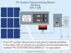
Means must be provided to disconnect the PV system from all wiring systems [Sec. 690.13]. The PV disconnect must be installed at a readily accessible location, and it must plainly indicate whether it’s in the on or off position and be permanently marked “PV SYSTEM DISCONNECT” [Sec. 690.13(B)] (Fig. 2).
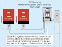
The PV system disconnecting means must consist of no more than six switches or six circuit breakers, mounted in a single enclosure or in a group of separate enclosures [Sec. 690.13(D)] (Fig. 3).
Wiring Methods
Any Chapter 3 wiring method, wiring and fittings listed for use on PV arrays, and wiring that’s part of a listed system are permitted for use on PV systems [Sec. 690.31(A)]. PV DC circuit conductors operating at more than 30V must be guarded or installed in Type MC cable or a raceway.
You can install PV source and output circuits (DC) in the same raceways or enclosure with each other, but not with feeders, branch circuits, or inverter output circuits (AC), unless the DC and AC circuits are separated by a partition [Sec. 690.31(B)]. PV DC circuit conductors must be identified at points of termination, connection, and splices.
Where the DC and AC conductors of more than one PV system occupy the same junction box or raceway with a removable cover(s), the AC and DC conductors of each system must be grouped separately by cable ties and then grouped at intervals not to exceed 6 ft [Sec. 690.31(B)(2)].
Exception: Grouping isn’t required if the PV circuit enters from a cable or raceway (unique to the circuit) that makes the grouping obvious.
PV source circuit conductor cable that’s listed and identified as PV wire can be run in exposed outdoors locations within the PV array where the conductors are guarded or they’re not readily accessible [Sec. 690.31(A) and Sec. 690.31(C)].
You can install jacketed multiconductor cable outdoors [Sec. 690.31(D)]. Jacketed cable assemblies must be secured at intervals not exceeding 6 ft.
Flexible cords and cables connected to moving parts of tracking PV must be hard service cord or portable power cable suitable for extra-hard usage, and listed for outdoor use as well as water-resistant and sunlight-resistant [Sec. 690.31(E)].
Single-conductor cables listed for outdoor use that are sunlight-resistant and moisture-resistant in sizes 16 AWG and 18 AWG are permitted for module interconnections where such cables meet the ampacity requirements of Sec. 400.5 [Sec. 690.31(F)].
PV system DC circuits run inside a building must be installed in a metal raceway, Type MC cable that complies with Sec. 250.118(10), or a metal enclosure. The wiring methods must also comply with the requirements of Sec. 690.31(G)(1) through (4).
Flexible, fine-stranded conductors must terminate in terminals, lugs, devices, or connectors identified and listed for fine-stranded conductors per Sec. 110.14 [Sec. 690.31(H)].
Where the sum of the PV system of two monopole subarrays exceeds the rating of the conductors and equipment, monopole subarrays must be physically separated, and the electrical output circuits from each monopole subarray must be installed in separate raceways until connected to the inverter.
The disconnecting means and OCPD for each monopole subarray output must be in separate enclosures [Sec. 690.31(I)].
PV systems must be clearly marked with a permanent, legible warning notice indicating that the disconnection of the grounded conductor(s) may result in overvoltage on the equipment.
Exception: Listed switchgear for bipolar systems rated for the maximum voltage between circuits with a physical barrier separating the disconnecting means for each monopole subarray can be used instead of disconnecting means in separate enclosures.
Grounding and Bonding
Almost all grounding and bonding requirements have changed since the previous NEC revision.
PV systems must be grounded via one or more of the six grounding configurations listed in Sec. 690.41(A)(1) through (6).
Equipment must be bonded per the requirements of Sec. 690.43(A), (B), and (C). For example, grounding conductors for the PV array and support structure must be within the same raceway or cable as the circuit conductors when those conductors leave the vicinity of the PV array [Sec. 690.41(C)].
Equipment grounding conductors (EGCs) for PV source and PV output circuits must be sized per Sec. 250.122, based on the rating of the circuit OCPD [Sec. 690.45].
Where no OCPD is provided for the PV source or PV output circuits, an assumed OCPD rated per Sec. 690.9(B) must be used when applying Table 250.122.
Where the requirements of Sec. 690.9(B) are both applied, the resulting multiplication factor is 156% of the module-rated short-circuit current.
If exposed EGCs sized 8 AWG and smaller are subject to physical damage, install them in a raceway [Sec. 250.120(C)].
Interactive Interconnection
The point of interconnection of the PV system to other power systems must be marked, at the PV system disconnecting means, with the inverter rated AC output current and nominal operating AC voltage [Sec. 690.54].
Power Source Identification
Any building or structure with a standalone PV system must have a permanent plaque or directory on the exterior of the building at a readily visible location. The plaque or directory must indicate the location of the standalone PV system disconnect and that the structure contains a standalone electrical power [Sec. 690.56(A)].
A permanent plaque or directory denoting the location of all electric power source disconnecting means must be installed at service equipment and PV system disconnecting means [Sec. 705.10]. The plaque or directory must be permanently affixed and have sufficient durability to withstand the environment involved [Sec. 110.21(B)].
Avoiding Problems
Correctly installing a PV system poses many challenges across several disciplines. To avoid problems with the electrical part of the installation, make sure you understand the PV system components, circuits, and connections. Figures 690.1(a) and (b) in the NEC can help you figure out what things are, where they go, and how they connect.
Also, note that Art. 690 underwent massive changes in the 2017 revision. Any project documentation (especially electrical drawings) created prior to the 2017 NEC should be reviewed and updated accordingly.
These materials are provided to us by Mike Holt Enterprises of Leesburg, Fla. To view additional Code training materials offered by this company, visit www.mikeholt.com.


