Harmonic Thd Graph

Where Is That Harmonic Source?

Sept. 22, 2020
Electrical current can point to a device that’s causing problems on a power system, but this isn’t always the case when there’s a harmonics issue.

Capacitors on power systems draw in higher frequency currents and can mislead an investigation. This article describes a way to find the source of a harmonic problem, but does not dive deep into a harmonics study itself, as there are existing articles and literature that provide that type of detailed information.

Briefly put, a single waveform capture can be mathematically broken down into its frequencies if the waveform is distorted. If there is no distortion in the waveform, then the only frequency that exists is the fundamental frequency. In the United States, the fundamental frequency is regulated at 60 Hz. Frequencies that are integer multiples of the fundamental frequency are known as harmonics. For example, assuming a 60-Hz fundamental frequency, the 2nd harmonic is 120 Hz, the 3rd harmonic is 180 Hz, the 5th harmonic is 300 Hz, and this continues on into the higher-order integers.

There are additional classifications that are identified but not covered in this article, which are sub-harmonics and interharmonics. Even-numbered harmonics are atypical and don’t appear often on the power system. What impacts the power systems are the odd ordered harmonics, such as the 3rd, 5th, 7, 9th, 11th, and so on. Odd ordered harmonics are typically generated by devices that have the capability of switching or chopping the incoming power to regulate voltage or drive the device. These devices can range from an LED lamp to a computer, all the way up to an adjustable speed drive (ASD) to run a motor.
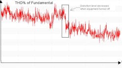
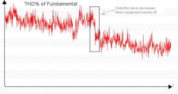
Before powering up a facility, it’s best to capture the harmonic distortion levels before the electrical equipment is brought online. This helps provide a point of reference to compare to when the facility is at full operation. A recommended tool for this is a monitoring device that can sample the total harmonic distortion (THD) levels and graph them on a time plot. As the THD levels start to vary, the time plot assists in indicating when a piece of equipment turned on, which would then reveal the suspected equipment. A caveat to this method is the complication of capacitors on the system. Due to the nature of capacitors, which includes power factor correction types, they can amplify the THD levels. Therefore, it is recommended that you turn off or disconnect capacitors when performing this study. Understandably, this may not be practical for some facilities.
About the Author

Vong Chan

Voice your opinion!

To join the conversation, and become an exclusive member of EC&M, create an account today!

Sponsored Recommendations

8 Types of Electrical Conduit and Their Uses

Electrical conduit is a tube or raceway used to house and protect electrical wires within a building or structure. From data centers to underground subways to ports and bridges...

A Powerful Duo: Fiberglass conduit and solar applications

Learn how strong, durable fiberglass conduit excelled in an environment with dense cable and helped make a complex burial much simpler for the contractor to help this customer...

Champion Fiberglass® Conduit Protects Cabling For New York's First Offshore Wind Farm

Learn how fiberglass conduit supported a heavy cable load and a buried installation to help this project reach a successful outcome.

How to Calculate Labor Costs

Most important to accurately estimating labor costs is knowing the approximate hours required for project completion. Learn how to calculate electrical labor cost.