Identifying Pitfalls in the Arc Flash Calculation Process
An electrical arc flash can occur when someone is verifying the presence of voltage, checking the balance of current, operating a switch, inspecting an energized cable or bus connections during routine maintenance, or simply standing in the vicinity of energized equipment. This is a reason to perform an arc flash hazard assessment study — to discern the degree of arc flash hazard present and the level of PPE required at a given location on the power distribution system. In addition, this type of study helps determine the possible means to reduce the energy through time and/or distance adjustments. Many times, however, this requires you to run through a series of calculations using available commercial engineering software or lengthy hand calculations. However, mistakes can be made during the calculations process. That’s why it’s critical for you to understand the limitations of these methodologies.
The basics
Arc flash studies require input from short circuit and coordination analysis to calculate incident energy based upon bolted and arcing fault current levels, arcing time duration, and distance to arc. Arcing faults are the result of current passing through the air. At a particular point in the distribution system, this current is always less than that possible for a bolted fault, which is a result of the direct metallic connection between conductors. The incident energy created during an arcing fault is calculated in the form of calories per square centimeter (cal/cm2).
The approach taken by the engineering professional performing the analysis needs to consider some items that are not necessarily addressed in performing short circuit and coordination analysis. This discussion will concentrate on the approach taken using IEEE Std 1584-2002 with two amendments: IEEE Std 1584a-2004 and 1584b-2011.
The objective of any arc flash assessment is to calculate the incident energy and determine the arc flash boundary distance. The arc flash boundary is defined as the approach limit, at a distance from exposed live parts, within which a person could receive a second-degree burn if an electrical arc flash were to occur. The reliability of overcurrent protective devices is critical to escalation of an arc flash to higher levels than expected, so system maintenance is very important.
Required data
An arc flash hazard assessment requires the following input data about the distribution system:
• Single-line diagram of the power distribution system from the electric utility source to the low-voltage panelboards and motors (50 hp and larger).
• Electric utility source data, indicating minimum and maximum available bolted fault current, X/R ratio, and supply voltage.
• Transformer data, indicating ratings, impedances, types, and primary/secondary protection.
• Equipment type and voltage rating of current transformers (CTs), breakers, switches, and fuses in switchgear, motor control centers (MCCs), and panelboards, indicating manufacturer, types, ratings, ratios, settings, and short circuit withstand capabilities.
• Protective device characteristics from time current curves (TCCs), indicating CT ratios, manufacturer, model, type, and settings.
• Feeder cable material (Cu/Al), sizes and lengths and raceway material (magnetic / non-magnetic).
• Size and rating of motors or loads, especially 40kW or larger, connected to switchgear, distribution panels, or MCCs.
• Working distance of worker to equipment bus or energized component.
Example scenario
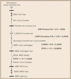
Let’s begin with a simple example of a radial portion of a distribution system (Fig. 1) having a 5kV overhead electric utility distribution line, using a pole-mounted fused disconnect, to feed an underground feeder serving an oil-filled, pad-mounted 1,500kVA transformer with 5.75% impedance. The primary full load ampacity (FLA) of the transformer is 208A. According to NEC Table 450.3(A), a primary fuse up to 300% could be used.
Let’s begin with a 500A, 5kV fuse, which is about 240% of primary FLA. There are cables connecting the 480/277V wye transformer secondary with a solidly grounded neutral to a main power circuit breaker in 480V switchgear. The secondary FLA of the transformer is 1,804A. Again, according to the NEC, a protective device could be sized up to 250% (in supervised locations), but a 125% limit (for unsupervised locations) is more common and useful for arc flash considerations. So 1.25 × 1,804A = 2,255A. However, because there is not a device of that rating, let’s begin with a 2,400A power circuit breaker. This main breaker could be set with a long time pick-up of 0.9 or 2,160A to properly protect the transformer and possibly the secondary conductors. One of the feeders from this switchgear is an 800A power circuit breaker feeding an 800A rated MCC. Finally, there is a 600A fused switch in the MCC serving a downstream panel load.
The primary conductors are routed in underground PVC conduits. The transformer primary is 100 ft of 2-250kcmil shielded copper 5kV conductors per phase with a 90°C conductor temperature — and each rated to carry 260A. The secondary conductors are routed in an underground ductbank, so you can use copper conductors with a 90°C conductor temperature using 6-500kcmil conductors per phase to carry the 1,804 FLA. However, these should be increased to 6-750kcmil per phase to carry 2,190A, which would then be protected by the secondary main breaker from a downstream fault. The conductors between the switchgear and the MCC are copper conductors with a 75°C conductor temperature in a steel conduit. Using 2-500kcmil per phase to carry 760A would allow the breaker to be set with a long time pick-up of 0.95 or 760A.
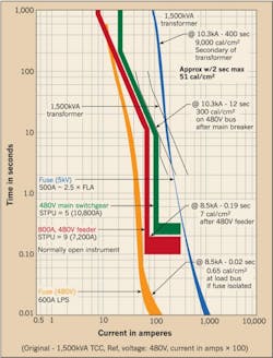
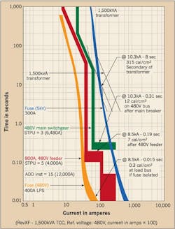
Once the available fault level is obtained from the electric utility, you can use the above data to evaluate the available fault levels at the switchgear and the MCC. In addition, when the equipment manufacturer and types of breakers are determined, a TCC can be prepared reflecting the operating conditions of this system (Fig. 2). Then, with the push of a button, if using commercially available software, the arc flash incident energy and arc flash boundary can be determined. But do you really have the necessary information for safe operation of the equipment at that point?
Other considerations
There are many locations within the power distribution system that are critical to appropriately understanding the exposure to arc flash energies. First, a device cannot protect itself. Thus, to evaluate the incident energy at any point, you must look upstream from the point of the fault to the protective device ahead of the point being evaluated. Second, to use the main to protect the bus during an arc flash, it must be physically isolated from the bus and from the downstream feeders.
To accomplish appropriate arc flash evaluation, one suggestion is to add buses (Fig. 3) at system connection points into the model. A bus could be added after any impedance item like a transformer or cable and before any protective device. A main breaker would have a bus shown on the input and output of the breaker. For our example, to calculate the arc flash energy at the main breaker, the primary fuse protecting the transformer must be investigated. However, to permit the main breaker to provide protection of the equipment bus and feeder breakers, it needs to be determined if the main breaker is isolated from the bus and feeder breakers (e.g., for switchgear).
In considering a distribution board with an included main, generally in a common enclosure with the bus and feeders, the main would not be considered isolated. The same is true for many switchboards, MCCs, and panelboards. One way to use a main to protect its downstream bus is to place the main in its own isolated enclosure and then use cable and conduit to the bus with fire stop in the conduit. The isolated main would have higher arc flash incident energy than the bus and downstream feeders.
Available fault current
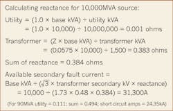
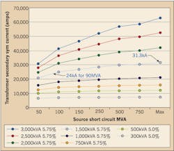
In the past, it was useful to consider an infinite electric utility short circuit current and then, from the transformer size and impedance, evaluate the maximum available bolted fault current. This was — and still is — helpful for ensuring the equipment has suitable short circuit withstand ratings. However, with arcing current being a lower current than the bolted fault current, it is also important to consider the actual or minimum available electric utility fault capacity. Compare the secondary available bolted fault current of a 10,000MVA source to a 90MVA source supplying a 480V, 1,500kVA transformer. Note that instead of a 31kA bolted fault, you could be looking at 24kA (Fig. 4). If you would plot a series of available source MVA versus transformer secondary faults, you could arrive at results depicted in Fig. 5.
However, it is not the bolted fault but the arcing fault that is important. It is well known that an arcing fault is lower in value than the available bolted fault for any point in a circuit. Using IEEE Std 1584 Equation 1 for under 1,000V, you can calculate that 480V equipment arcing faults are roughly between 40% and 60% of the available bolted fault current level. For quick calculations, a value of 50% can be used. For 208V equipment, arcing faults are roughly between 20% and 35% of the available bolted fault. For quick estimated calculations, a value of 25% can be used.
In addition, according to IEEE Std 1584, there is a recommendation to calculate a second arc current equal to 85% of the calculated arcing fault current. This is done to allow for discrepancies in matching the equation to the test points. Then, from the bolted fault, the arcing fault and 85% of the arcing fault can be estimated.
Arcing faults are not predictable
Let’s recap what we’ve discussed so far. The electric utility is asked to provide an estimate of the fault current at the point in its system where the equipment that is being evaluated is said to exist (the position of which is an estimate). You use the manufacturer’s estimate of the transformer impedance, which varies from no load to full load — and with temperature. The conductor size and length are chosen, and, as a result, its impedance is estimated — again, as it varies with temperature. Calculations provide an estimate of the bolted fault current and subsequently estimate the arcing fault current. Manufacturers’ estimated TCCs depict how a properly maintained protective device is expected to respond to the bolted and arcing fault current. In other words, our resulting calculation is a reasonable approximation of what is expected to occur.
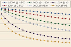
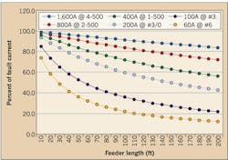
Expanding our facility distribution system to include bolted and arcing fault levels, it should be realized that the fault current also has an impact on the conductors’ ability to transmit that level of fault current. If a fault current of 24kA is available at the transformer secondary, then a conductor rated to normally carry a full load current could experience a lower fault current at a distance from the source to an estimated point by as much as 200 ft (Fig. 6). With a 24kA available bolted fault, an 800A feeder circuit of 100 ft for the MCC would only see 83% of that available fault, or 20kA; and the arcing fault would be roughly 50%, or 10kA. The 85% point is 8.5kA. So what started as 24kA is now seen as 8.5kA. This certainly has an impact on the setting of the circuit protective device.
Mitigation
What can be adjusted to affect the arc flash incident energy in a system? The fault level from the electric utility can’t be modified by the facility distribution system. The transformer size and impedance can be adjusted, especially for large units, but this may not allow for the appropriate total capacity of service to the facility. The location of equipment could be adjusted, but other factors generally have the principal impact on equipment location. The electrical protective devices and their settings can be selected and have the greatest effect on the available incident energy at points throughout the distribution system.
Looking back at the initial system TCC (Fig. 2), can anything be adjusted to reduce the arc flash incident energies in the system? The primary fuse could be resized. This would still allow for transformer inrush and full load capability. In general, medium-voltage fuses do not provide a real means to reduce incident energy, especially on the low-voltage side of the transformer.
For the 1,500kVA transformer with a 90MVA source, there is 12.5kA bolted fault current at 4,160V. The medium-voltage arcing fault is roughly 1% to 2% less than the bolted fault per Equation 2 of IEEE Std 1584. Then, looking at 85%, the 4,160V arcing fault level is approximately 10.6kA. A 500A fuse would respond in about 0.02 sec, yielding an arc flash energy at the transformer primary of less than 1cal/cm2. The secondary 24.3kA of bolted fault at 480V would have about 12kA of arcing fault and 10.3kA of reduced arcing fault. The medium-voltage fuses respond much too slowly, resulting in energy above 50 cal/cm2. However, looking at Fig. 7, the short-time pickup (STPU) of the secondary main could be reduced from 5 to 3. This would reduce the reaction time for the main breaker from 12 sec to 0.31 sec and thus, the arc flash incident energy from 50 cal/cm2 (for 2 sec maximum) to 12 cal/cm2. The MCC feeder STPU could be reduced from 9 to 5 to maintain coordination with the main. This would overlap the 600A fuse, but if the fuse size could be reduced to 400A, coordination would be maintained.
Option for Class L fuses
During this design, you could use other protective devices, such as a 2,000A secondary main fuse. When large low-voltage fuses are used, they respond in about 1 sec to a fault at seven to eight times their FLA rating and in about 0.01 sec to about 15 times their FLA rating. Keeping in mind that the arcing fault level is less than the bolted fault level (about 10kA for our example), a 2,000A secondary Class L fuse would respond to the arcing fault in about 7 sec. In fact, smaller fuses (even of the same current rating) of different types have differing responses at various current levels.
Various breaker types
Breakers also have differing characteristics. For example, an 800A adjustable power circuit breaker and an 800A thermal magnetic breaker are quite different. The power circuit breaker has long time (LTPU & LTD), short time (STPU & STD), and instantaneous (INST) settings, as well as, I2t and zone selective interlock options. The thermal magnetic breaker typically has LTPU and INST settings with possible adjustment of the INST (5 to 10 or some similar range) and possible zone selective interlock option.
It should be noted, with experience, that 480V equipment reaction times over approximately 0.5 sec for bolted fault values above 42kA — and reaction times of 1 sec for bolted fault values above 22kA — result in PPE Class 4 protective clothing level or higher.
In addition to the re-evaluation of protective devices and their settings, there are other mitigation approaches to consider:
• Replace the medium-voltage fuse or add a medium-voltage breaker with a short time adjustment to reduce secondary arc fault energy.
• Add a maintenance switch to provide lower relay settings or an instantaneous adjustment to a lower fault pick-up level in accordance with the arcing current.
• Add an arc mitigation relay that senses a flash of light from an arcing fault and the rate of rise of the current from the fault.
• Provide a reactor in the distribution circuit to reduce a high fault current
• Use zone selective interlocking to recognize and localize a fault more quickly.
• Install an ultra-fast earthing switch (UFES) between the medium-voltage fuse and transformer primary.
In many situations, the above may require an alternate scenario to the original design.
Increase the distance to equipment especially during operating and racking procedures:
• Provide a longer cranking rod to rack breakers. At 480V, doubling a nominal 18-in. distance would reduce the energy to about one-third. At 15kV, doubling a nominal 24-in. distance would reduce the energy about in half.
• Provide a remote racking device.
• Provide a remote operator.
Other non-direct effects on incident energy:
• Be aware of standby generators having lower available fault current than the electric utility power feed.
• Install arc resistant switchgear (Note: This equipment is only arc resistant when the doors are closed).
• A neutral grounded resistor (must be supervised) reduces the magnitude of single-phase arcs.
• Insulate the bus, which reduces the probability for single-phase and 3-phase arcs.
Conclusion
Although arc flash is a serious workplace hazard, there are means to evaluate its intensity and to mitigate the affect on electrical workers. IEEE Std 1584 and NFPA-70E provide mechanisms to calculate its intensity and to recommend appropriate PPE. Engineers should also be encouraged to determine other effective mitigation techniques such as providing barriers, increasing working distance from an arc, and reducing the time an arc would exist.
Scherry is a registered professional electrical engineer with Scherry Engineering and Consulting, Inc. in St. Louis. He can be reached at [email protected].