Circuits that fall under the requirements of Art. 725 are remote-control, signaling, and power-limited circuits that aren’t an integral part of a device or appliance. Article 725 includes circuits for burglar alarms, access control, sound, nurse call, intercoms, some computer networks, some lighting dimmer controls, and some low-voltage industrial controls.
Let’s take a quick look at the types of circuits involved:
• A remote-control circuit controls other circuits through a relay or solid-state device, such as a motion-activated security lighting circuit.
• A signaling circuit provides output that’s a signal or indicator, such as a buzzer, flashing light, or annunciator.
• A power-limited circuit is supplied by a transformer or other power source that limits the amount of power to provide safety from electrical shock and/or fire ignition.
The purpose of Art. 725 is to allow for the fact that these circuits “are characterized by usage and power limitations that differentiate them from electrical power circuits” [725.1 Informational Note]. This Article provides alternative requirements for minimum conductor sizes, overcurrent protection, insulation requirements, wiring methods, and materials.
Article 725 consists of four parts. Part I provides general information, Part II pertains to Class 1 circuits, Part III addresses Class 2 and Class 3 circuits, and Part IV focuses on listing requirements. The key to understanding and applying each of these Parts is in knowing the voltage and energy levels of the circuits, the wiring method involved, and the purpose(s) of the circuit.
What’s a Class 1 circuit?
The NEC defines it as that wiring system between the load side of the overcurrent device or power-limited supply and the connected equipment such as relays, controllers, lights, audible devices, and so forth. What’s a power-limited supply? The source has a rated output of not more than 30V and 1,000VA [725.41(A)]. Class 1 nonpower-limited circuits can operate at up to 600V and the power output isn’t limited [725.41(B)].
Other Articles
Generally, the first four Chapters of the NEC apply to all electrical installations except as modified by later Chapters. But with Art. 725, it works somewhat in reverse; only those sections contained in Art. 300 specifically referenced in Art. 725 apply to Class 1, 2, and 3 circuits [725.3].
The number and size of conductors or cables in a raceway are limited per Sec. 300.17. Raceways must be large enough to permit the installation and removal of conductors without damaging conductor insulation. When all conductors in a raceway are the same size and insulation, the number of conductors permitted can be found in Annex C for the raceway type [725.3(A)].
Let’s take a look at an example situation to clarify this point.
How many 18 AWG TFFN fixture wires can be installed in trade size ½ electrical metallic tubing? Finding the answer is as simple as checking Table C.1 in Annex C. A quick glance of the table reveals the answer of 22 conductors.
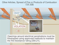
Class 1, 2, and 3 circuits installed through fire-resistant-rated walls, partitions, floors, or ceilings must be firestopped to limit the possible spread of fire or products of combustion in accordance with the specific instructions supplied by the manufacturer for the specific type of cable and construction material (drywall, brick, and so on) [725.3(B), 300.21] (Fig. 1 Class 1, 2, and 3 circuits in cable trays must be installed per Art. 392 [725.3(E)].
Class 1 circuit classifications and power-supply requirements
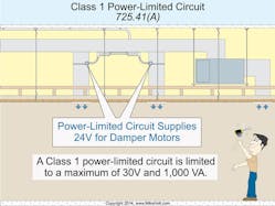
Class 1 power-limited circuits must be supplied from a power supply that limits the output to 30V with no more than 1,000VA [725.41(A)] (Fig. 2). But it’s also important to point out that Class 1 power-limited circuits aren’t that common. They’re used when the voltage must be less than 30V (safe from electric shock in dry locations), and where the power demands exceed the 100VA energy limitations of Class 2 or Class 3 circuits, such as for motorized loads like remote-controlled window blinds [Chapter 9, Table 11(A)].
Class 1 remote-control and signaling circuits must not operate at more than 600V, and the power output of the power supply isn’t required to be limited [725.41(B)].
Class 1 circuit overcurrent protection
Overcurrent protection for conductors 14 AWG and larger must be in accordance with the conductor ampacity, without applying the ampacity adjustment or correction factors of Sec. 310.15, and overcurrent protection must not exceed 7A for 18 AWG conductors and 10A for 16 AWG [725.43].
Class 1 circuit wiring methods
Class 1 circuits must be installed per Part I of Art. 300, and Class 1 wiring must be installed using Chapter 3 wiring methods [725.46]. Class 1 circuits must be installed in a suitable Chapter 3 wiring method and splices must be contained in enclosures [300.15].
Conductors of different circuits in same cable, cable tray, enclosure, or raceway
Class 1 circuits can be installed with other circuits as follows [725.48]:
(A) Class 1 circuits with other Class 1 circuits. Two or more Class 1 circuits can be installed in the same cable, enclosure, or raceway.
(B) Class 1 circuits with power-supply circuits. Class 1 circuits are permitted with electrical power conductors in accordance with the following:
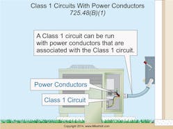
(1) In a cable, enclosure, or raceway. Class 1 circuits can be in the same cable, enclosure, or raceway with power-supply circuits, if the equipment powered is functionally associated with the Class 1 circuit (Fig. 3).
(2) In factory- or field-assembled control centers. Class 1 circuits can be installed in control centers, either in the factory or in the field.
(3) In a manhole. There are three conditions enumerated for this. First, the conductors must be in a metal-enclosed cable or Type UF cable. Second, the conductors must be permanently separated from the power-supply conductors by a continuous firmly fixed nonconductor, such as flexible tubing, in addition to the insulation on the wire. Third, the conductors must be permanently and effectively separated from the power supply conductors and securely fastened to racks, insulators, or other approved supports.
(4) In cable trays. Class 1 circuits not functionally associated with power conductors:
(1) Must be separated by a solid fixed barrier of a material compatible with the cable tray, or
(2) Be installed in Type AC, Type MC, Type MI, or Type TC cables (and all the conductors in the cables are insulated at 600V or greater).
Class 1 circuit conductors
Conductors of sizes 18 AWG and 16 AWG installed in a raceway, enclosure, or listed cable are permitted if they don’t supply a load that exceeds the ampacities given in Sec. 402.5. Conductors 14 AWG and larger must not supply loads greater than the ampacities given in Sec. 310.15 [725.49(A)].
Class 1 circuit conductors must have at least a 600V insulation rating. Conductors larger than 16 AWG must comply with Art. 310 [725.49(B)].
Conductor insulation in sizes 18 AWG and 16 AWG must be type FFH-2, KF-2, KFF-2. PAF, PAFF, PF, PFF, PGF, PGFF, PTF, PTFF, RFH-2, RFHH-2, RFHH-2, RFHH-3, SF-2, SFF-2, TF, TFF, TFFN, TFN, ZF, or ZFF [725.49(B)].
Number of conductors in a raceway
Raceways must be large enough to permit the installation and removal of conductors without damaging conductor insulation as limited by Sec. 300.17 [725.51]. When all conductors in a raceway are the same size and insulation, the number of conductors permitted can be found in Annex C for the raceway type.
The ampacity adjustment factors of Table 310.15(B)(3)(a) apply only to Class 1 circuit conductors carrying continuous loads in excess of 10% of the ampacity of each conductor [725.51(A)].
Extending beyond one building
If your Class 1 circuits extend aerially beyond one building, they must also meet the requirements of Art. 225 [725.52].
Staying at the head of the class
Meeting the requirements for Class 1 circuits isn’t particularly difficult, but they are often installed alongside Class 2 or 3 circuits. It’s not uncommon to run a Class 1 circuit through a ceiling space that contains a Class 2 power supply. So it’s easy to confuse these various circuits.
To avoid a mix-up, always identify the power source of the specific circuit you’re working with. A Class 1 source is either a power-limited supply such as a transformer (it has a rated output of not more than 30V and 1,000VA) or an overcurrent device (nonpower-limited and can operate at up to 600V).
These materials are provided to us by Mike Holt Enterprises in Leesburg, Fla. To view Code training materials offered by this company, visit www.mikeholt.com/code
