NEC Requirements for Energy Storage Systems
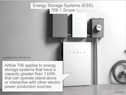
Article 706 applies to energy storage systems (ESSs) that have a capacity greater than 1kWh and that can operate in stand-alone (off-grid) or interactive (grid-tied) mode with other electric power production sources to provide electrical energy to the premises wiring system (Fig. 1). ESSs can have many components, including batteries and capacitors. They include inverters or converters to change voltage levels or to make a change between an alternating-current and a direct-current system.
Only qualified persons may install or maintain an ESS [Sec. 706.3]. Each ESS must be listed [Sec. 706.5] and have eight bits of data marked on a nameplate, for example rated frequency and rating in kW or kVA [Sec. 706.4].
Multiple ESSs are permitted on the same premises [Sec. 706.6]. As with PV systems, ESSs may be composed of multiple pieces of equipment assembled into a single system, or each piece of equipment may be considered an ESS on its own. The best way to identify an ESS is to look for a nameplate and review the instructions, both of which are part of the equipment’s listing.
Commissioning and maintenance
For other than one- and two-family dwellings, ESSs must be commissioned upon installation [Sec. 706.7(A)]. NFPA 855, Standard for the Installation of Stationary ESS, guides commissioning.
For other than one- and two-family dwellings, ESSs must be maintained in proper and safe operating condition as per manufacturer and industry standards [Sec. 706.7(B)]. A written (this includes computerized) record of repairs and replacements must be kept.
For information on developing an effective electrical preventive maintenance program, see NFPA 70B, Recommended Practice for Electrical Equipment Maintenance, or ANSI/NETA ATS-2017, Standard for Acceptance Testing Specifications for Electrical Power Equipment and Systems.
Disconnecting Means
A disconnecting means must be provided to disconnect the ESS from other sources of power, utilization equipment, and premises wiring [Sec. 706.15(A)].
In other than one- or two-family dwelling units, the disconnect marking must include the identification and location of the circuit source that supplies the disconnect unless located and arranged so the identification and location of the circuit source is evident [Sec. 110.22]. The marking must be sufficiently durable to withstand the environment involved.
The ESS disconnect must be readily accessible and located either within the ESS or within sight of (and not more than 10 ft from) the ESS [Sec. 706.15(B)].
Where the disconnect is not within sight of the ESS, the disconnect (or the enclosure providing access to the disconnect) must be capable of being locked in the open position per Sec. 110.25.
In one- and two-family dwellings, the ESS must include an emergency shutdown function to cease power export from the ESS to premises wiring. The initiation device for the ESS emergency shutdown function must be in a readily accessible location outside the building (Fig. 2).
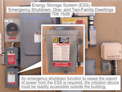
The ESS emergency shutdown initiation device must plainly indicate whether it is in the “off” or “on” position.
The requirements in Sec. 706.15(A) can be met with disconnects that are integral to the listed ESS equipment. Since an ESS application may have multiple individual ESS units, each may require a disconnect, but this does not necessarily mean each will require a separate disconnect switch adjacent to the units. Many ESS manufacturers choose to incorporate a means of disconnect into their ESS units. These disconnects are evaluated during the system’s listing.
The ESS disconnect must plainly indicate whether it is in the open (off) or closed (on) position and be marked “ENERGY STORAGE SYSTEM DISCONNECT” [Sec. 706.15(C)].
For other than one- and two-family dwellings, the ESS disconnect must be legibly marked to withstand the environment involved and include nominal battery voltage, available fault current, an arc-flash label per acceptable industry practice, and the date the arc-flash calculation was performed.
Information Note 1: Industry practices for equipment labeling are described in NFPA 70E, Standard for Electrical Safety in the Workplace. This standard provides specific criteria for developing equipment arc-flash labels that provide nominal system voltage, incident energy levels, arc-flash boundaries, minimum required levels of personal protective equipment, and so forth.
Information Note 2: ESS electronics could include inverters or other types of power conversion equipment.
If line and load terminals within the ESS disconnect could be energized in the open position, the disconnect must be marked: “WARNING ELECTRIC SHOCK HAZARD TERMINALS ON THE LINE AND LOAD SIDES MAY BE ENERGIZED IN THE OPEN POSITION.”
The marking must have sufficient durability to withstand the environment involved [Sec. 110.21(B)].
Where ESS circuits pass through a wall, floor, or ceiling, a readily accessible disconnect within sight of the ESS is required [Sec. 706.15(D)].
This provision will not apply to every ESS application where circuit conductors travel through walls, floors, or ceilings. It is for those applications (typically large ones) where the battery is in one room and other equipment that is part of the ESS is in another. In those cases, a disconnect must be in the room containing the battery. This does not apply to situations where the entire ESS is in one room and the output circuit from the ESS connects to other systems in other rooms. In those cases, the disconnect location requirements in Sec. 706.15(A) are all that apply.
Batteries could include an enclosure, battery monitoring and controls, or other related battery components. Where the battery of the ESS is separate from the electronics and subject to field servicing, the following applies [Sec. 706.15(E)]:
- A readily accessible disconnect is required within sight of the battery. See Sec. 240.21(H) for information on the location of the overcurrent protective device (OCPD) for battery conductors.
- Where the battery disconnect has remote controls not within sight of the battery, the battery disconnect must be capable of being locked in the open position per Sec. 110.25, and the location of the controls must be field marked on the battery disconnect.
- The battery disconnect must be legibly marked to withstand the environment involved and include nominal battery voltage, available fault current, an arc-flash label per acceptable industry practice, and the date the arc-flash calculation was performed.
Paralleled with other power sources
ESSs in parallel with other power sources must comply with the following [Sec. 706.16]:
(A) All power sources must have a disconnecting means.
(B) All power sources must use interactive (grid-tied) inverters.
(C) Upon loss of electric utility power, the interactive (grid-tied) inverter must automatically disconnect from the electric utility per Sec. 705.40.
(D) Unbalanced AC connections must comply with Sec. 705.45.
(E) The parallel connection of the ESS to other power sources must be per Sec. 705.12.
(F) Where the ESS is operating in stand-alone (off-grid) mode, the requirements of Sec. 710.15 apply.
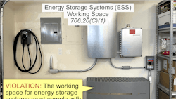
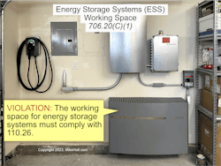
Working spaces
The working space about ESSs must comply with Sec. 110.26 (Fig. 3).
ESSs must be spaced apart per the manufacturer’s instructions [Sec. 706.20(C)(2). Additional space may be needed to accommodate ESS hoisting equipment, tray removal, or spill containment.
Circuit current rating
The maximum current for an ESS is as follows [Sec. 706.30(A)]:
(1) Nameplate-Rated Circuit Current. The rated current indicated on the ESS nameplate.
(2) Inverter Output Current. The continuous inverter output AC current rating.
(3) Inverter Input Current. The continuous inverter input DC current at the lowest input voltage.
(4) Inverter Utilization Output Circuit Current. The continuous inverter output AC current rating.
(5) DC-to-DC Converter Output Current. The continuous DC-to-DC converter’s nameplate current rating.
Conductor ampacity
The ampacity of the output circuit conductors of the ESSs to the wiring system supplying the load must be at least 125% of the current rating of the ESS per Sec. 705.30(A) or the rating of the OCPD [Sec. 706.31].
Overcurrent protection
OCPDs must be compliant per Sec. 706.31(B) through (F). For example, OCPDs must have an ampere rating of at least 125% of the current marked on the ESS nameplate [Sec. 706.30(A)]
Exception: Where the assembly (including the OCPDs) is listed for operation at 100% of its rating, the ampere rating of the OCPDs can be not less than the currents calculated in Sec. 706.30(B).
For a smooth start-up
Once your ESS is installed, it must be commissioned — but don’t wait until commissioning to discover engineering errors and Code violations that can result in scheduling delays and cost overruns. Review the commissioning plan well ahead of time. Do a dry run of the relevant parts of the plan as you work on specific stages of the project, correcting errors as you find them.
These materials are provided by Mike Holt Enterprises in Leesburg, Fla. To view Code training materials offered by this company, visit www.mikeholt.com/code.

About the Author

Mike Holt
Mike Holt is the owner of Mike Holt Enterprises (www.MikeHolt.com), one of the largest electrical publishers in the United States. He earned a master's degree in the Business Administration Program (MBA) from the University of Miami. He earned his reputation as a National Electrical Code (NEC) expert by working his way up through the electrical trade. Formally a construction editor for two different trade publications, Mike started his career as an apprentice electrician and eventually became a master electrician, an electrical inspector, a contractor, and an educator. Mike has taught more than 1,000 classes on 30 different electrical-related subjects — ranging from alarm installations to exam preparation and voltage drop calculations. He continues to produce seminars, videos, books, and online training for the trade as well as contribute monthly Code content to EC&M magazine.