NEC Requirements for Sizing Junction Boxes and Pull Boxes
Conductor damage during installation is one consequence of under sizing junction and pull boxes. This damage is often not apparent until post-installation cable testing. Then, after the boxes are replaced, the defective conductors are replaced. This is an inefficient and expensive way to do an electrical installation.
So, while the NEC box size requirements help to prevent hazards to people and property, following them also contributes to on-time job completion, reduced waste, and staying on budget.
Sizing Rules
You must size pull boxes, junction boxes, and conduit bodies large enough so a crew can install the conductors without damaging them. For conductors
4 AWG and larger, you size pull boxes, junction boxes, and conduit bodies per Sec. 314.28. That means the minimum dimensions of boxes and conduit bodies must comply with the following:
• Straight pulls. A conductor that enters one wall of a box and leaves through the opposite wall is a straight pull. The minimum distance from the raceway entry to the opposite wall is eight times the trade size of the largest raceway.
• Angle pulls. A conductor that enters one wall and leaves through an adjacent one is an angle pull. The minimum distance from the raceway entry to the opposite wall is six times the trade size of the largest raceway, plus the sum of the trade sizes of the remaining raceways on the same wall and row.
• U pulls. A conductor that enters and leaves from the same wall is a U pull. The minimum distance from the raceway entry to the opposite wall is six times the trade size of the largest raceway, plus the sum of the trade sizes of the remaining raceways on the same wall and row.
• Splices. When conductors are spliced, the minimum distance from where the raceways enter to the opposite wall is six times the trade size of the largest raceway, plus the sum of the trade sizes of the remaining raceways on the same wall and row.
• Rows. Where there are multiple rows of raceway entries, you calculate each row individually and then use the row that results the largest distance calculation.
• Distance between raceways. The minimum distance between raceways enclosing the same conductor is six times the trade size of the largest raceway, measured from the nearest edge of one raceway entry to the nearest edge of the other raceway entry. The locknut or bushing doesn’t apply to this calculation.
When conductors enter an enclosure with a removable cover, such as a conduit body or wireway, the minimum distance from the raceway entry to the removable cover is the bending distance listed in Table 312.6(A) for one conductor per terminal [Sec. 314.28(A)(2) Exception, Sec. 366.58, Sec. 376.23, and Sec. 378.23].
Pull Box Example 1
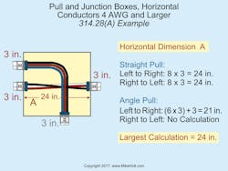
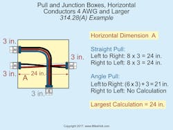
A junction box contains two 3-in. raceways on the left side, one 3-in. raceway on the right side, and one 3-in. raceway on the bottom. The conductors from the lower 3-in. raceway on the left wall are pulled through the 3-in. raceway on the right wall. The conductors from the upper 3-in. raceways on the left wall are pulled through the 3-in. raceway at the bottom of the pull box. Tip: Carefully draw the junction box, raceways and where the conductors are run.
Horizontal dimension
What’s the horizontal dimension of this junction box (Fig. 1)?
Left to Right Straight Pull = 8 × 3 in. = 24 in.
Right to Left Straight Pull = 8 × 3 in. = 24 in.
Left to Right Angle Pull = (6 × 3 in.) + 3 in. = 21 in.
Right to Left Angle Pull = No Calculation
Therefore, the minimum horizontal dimension of this junction box is 24 in.
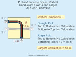
Vertical dimension
What’s the vertical dimension of this junction box (Fig. 2)?
Top to Bottom Straight = No Calculation
Bottom to Top Straight = No Calculation
Top to Bottom Angle = No Calculation
Bottom to Top Angle = 6 × 3 in. = 18 in.
Therefore, the minimum vertical dimension of this junction box is 18 in.
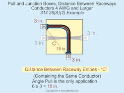
Distance between raceways
What’s the minimum distance between the two 3-in. raceways containing the same conductors (Fig. 3)?
Answer = 6 × 3 in. = 18 in.
Pull Box Example 2
A pull box contains a 2-in. and a 3-in. raceway on the left side, a 3-in. raceway on the top, and a 2-in. raceway on the right side. The 2-in. raceways are a straight pull and the 3-in. raceways are an angle pull. Remember: Draw the junction box, raceways and where the conductors are run.
Horizontal dimension
What’s the horizontal dimension of this junction box?
Left to Right Straight Pull = 8 × 2 in. = 16 in.
Right to Left Straight Pull = 8 × 2 in. = 16 in.
Left to Right Angle Pull = (6 × 3 in.) + 2 in. = 20 in.
Right to Left Angle Pull = No Calculation
Therefore, the minimum horizontal dimension of this junction box is 20 in. [314.28(A)(2)]
Vertical dimension
What’s the vertical dimension of this junction box?
Top to Bottom Straight = No Calculation
Bottom to Top Straight = No Calculation
Top to Bottom Angle = 6 × 3 in. = 18 in.
Bottom to Top Angle = No Calculation
Therefore, the minimum vertical dimension of this junction box is 18 in. [314.28(A)(2)]
Distance between raceways
If two 3-in. raceways contain the same conductors, what’s the minimum distance between these raceways?
Answer = 6 × 3 in. = 18 in. [314.28(A)(2)]
Sizing Tips for Pull Boxes and Junction Boxes
When sizing pull boxes and junction boxes, follow these suggestions:
Step 1: Organize and always draw out the problem.
Step 2: Calculate the horizontal distance(s):
• Left to right straight calculation
• Right to left straight calculation
• Left to right angle or U pull calculation
• Right to left angle or U pull calculation
Step 3: Calculate the vertical distance(s):
• Top to bottom straight calculation
• Bottom to top straight calculation
• Top to bottom angle or U pull calculation
• Bottom to top angle or U pull calculation
Step 4: Calculate the distance between raceways enclosing the same conductors.
Know the System
These rules are based on the characteristics of standard electrical conductors and thus apply only to raceway systems for electrical conductors. Many types of cables, such as fiber-optic for example, have a much higher minimum bend radius than electrical conductors of the same diameter. You don’t size the boxes for these as if you were installing electrical power conductors.
Often, the same engineering team is tasked with all the box sizing for all systems. If all the box sizing is based on Sec. 314.28 regardless of what’s being run, the boxes will probably be undersized for raceway systems containing signal cabling or anything other than electrical power conductors.
At an Ohio nuclear power plant, some signal cables for the reactor protection system had a 3-ft bend radius but were run in raceway with 18-in. boxes based on NEC requirements for electrical power conductors. The mere act of pulling the cables into those boxes damaged the cables and caused them to fail the acceptance testing.
The cables were very costly, so after the first test showed a 100% failure rate, the reactor protection system test engineers stopped testing to investigate possible failure causes. During a walk-thru, they saw the undersized pull box. The design engineer would not have made this mistake if he’d clearly separated the electrical power conductor raceway system design from signal cabling raceway system design.
Perhaps the most important thing you can do when sizing boxes is to make sure you understand the application. We mentioned you need to avoid applying NEC box sizing rules to signal cabling systems. Another aspect of the application is to understand the application environment. For example, will the box fit at the location you’ve selected for it? Can it safely and reasonably be serviced there? Never attempt to design in an information vacuum. Know the system; that’s what requests for information are for!
These materials are provided to us by Mike Holt Enterprises of Leesburg, Fla. To view additional Code training materials offered by this company, visit www.mikeholt.com.About the Author

Mike Holt
Mike Holt is the owner of Mike Holt Enterprises (www.MikeHolt.com), one of the largest electrical publishers in the United States. He earned a master's degree in the Business Administration Program (MBA) from the University of Miami. He earned his reputation as a National Electrical Code (NEC) expert by working his way up through the electrical trade. Formally a construction editor for two different trade publications, Mike started his career as an apprentice electrician and eventually became a master electrician, an electrical inspector, a contractor, and an educator. Mike has taught more than 1,000 classes on 30 different electrical-related subjects — ranging from alarm installations to exam preparation and voltage drop calculations. He continues to produce seminars, videos, books, and online training for the trade as well as contribute monthly Code content to EC&M magazine.


