Article 445 contains the electrical installation and other requirements for generators, including such things as where generators can be installed, nameplate markings, conductor ampacity, and disconnecting means. Generators are basically motors that operate in reverse, producing electricity when rotated, instead of rotating when supplied with electricity.
Article 430, which covers motors, is the longest article in the NEC. Article 445, which covers generators, is one of the shortest. At first, this might not seem to make sense. But you don’t need to size and protect conductors to a generator. You do need to size and protect them to a motor.
Generators need overload protection, and it’s necessary to properly size the conductors that come from the generator. But these considerations are much more straightforward than the equivalent considerations for motors.
To correctly apply Art. 445, it helps to know the definition of a “separately derived system.” That definition is spelled out in Art. 100 as follows: “An electrical source, other than a service, having no direct connection(s) to circuit conductors of any other electrical source other than those established by grounding and bonding connections.” Understanding this definition is also critical to correctly applying Art. 250 (Grounding and Bonding) requirements to generator installations. Not every generator is a separately derived source.
Generators, associated wiring, and equipment must be installed per the following requirements depending on their use:
- Fire Pumps (Art. 645)
- Emergency Systems (Art. 700)
- Legally Required Standby Systems (Art. 701)
- Optional Standby Systems (Art. 702)
Overcurrent protection
The overcurrent protection requirements are not the same for all types of generators. The NEC recognizes these five types:
1. Constant voltage generators must be protected from overload by inherent design, circuit breakers, fuses, or other identified overcurrent protective means [Sec. 445.12(A)].
2. Two-wire, DC generators can have overcurrent protection in just one conductor — but only if the overcurrent device is actuated by the entire current generated other than the current in the shunt field. The overcurrent device (OCPD) must not open the shunt field [Sec. 445.12(B)].
3. Generators operating at 65V or less and driven by individual motors must be considered protected by the overcurrent device(s) protecting the motor — but only if these devices will operate when the generators are delivering not more than 150% of their full-load rated current [Sec. 445.12(C)].
4. Two-wire, DC generators used in conjunction with balancer sets to obtain neutral points for 3-wire systems must be equipped with overcurrent devices that disconnect the 3-wire system in case of excessive unbalancing of voltages or currents [Sec. 445.12(D)].
5. Three-wire, DC generators, whether compound or shunt wound, must be equipped with overcurrent devices. There must be one in each armature lead, and it must be connected so it’s actuated by the entire current from the armature [Sec. 445.12(E)].
Note that an exception to Sec. 445.12(A) through (E) exists. Instead of interrupting the circuit, the overload sensing device(s) may be connected to an annunciator or alarm supervised by authorized personnel if certain requirements are met. What are those requirements?
The authority having jurisdiction (AHJ) must deem that a generator is vital to the operation of an electrical system, and the generator should operate to failure (rather than be protected) to prevent a greater hazard to persons.
Your generator might not be vital to the operation of an electrical system, but that doesn’t mean its function isn’t important. If the overcurrent protective devices (OCPDs) are fuses, an inexpensive downtime reduction measure is the practice of having spare fuses located near the generator. Inside a pouch in the control cabinet might be the perfect spot.
If there’s not a box of foam roll-up earplugs near the door to the generator room, get one up there. It’s one less thing that can interfere with handling generator problems when the main power is down or under some other circumstance in which you really need to get that generator running.
Conductor ampacity
The ampacity of the conductors from the generator winding output terminals to the first overcurrent protection device, typically on the generator, must have an ampacity of not less than 115% of the nameplate current rating of the generator [Sec. 445.13(A)]. Since the overcurrent protection device is typically part of the generator, this rule applies to the generator manufacturer, not the field installer.
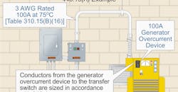
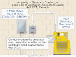
When sizing the conductors from the load side of the generator overcurrent protection device to the transfer switch, size them per Sec. 240.4.
Example: What size conductor is required from a 100A overcurrent protection device on a 20kW, 120/240V single‑phase generator to a 200A service rated transfer switch if the terminals are rated for 75°C conductor sizing (Fig. 1)?
Answer: A 3 AWG conductor is required; Table 310.15(B)(16), rated 100A at 75°C [Sec. 110.14(C)(1)(b)].
Generators that aren’t a separately derived system [Art. 100] must have the neutral conductor sized to carry the maximum unbalanced current as determined by Sec. 220.61, serve as part of the effective ground‑fault current path, and not be smaller than required by Sec. 250.30 (Fig. 2).
Where the generator set is equipped with a listed OCPD or a combination of a current transformer and overcurrent relay, conductors can be tapped from the load side of the generator OCPD per Sec. 240.21(B) [445.13(B)]. Tapped conductors are not permitted for portable generators rated 15kW or less where field wiring connection terminals are inaccessible.
Live parts
For generators that operate at more than 50VAC or 60VDC to ground, live parts shall not be exposed to accidental contact where accessible to unqualified persons [Sec. 445.14]. One way (among others) to meet this rule is to locate the generator in a locked room with key card access. That way, only qualified persons can get near the generator. That not only protects unqualified persons from your generator, but it also protects your generator system from unqualified persons.
You should also evaluate the system to determine if guards are necessary for the protection of attendants. If so, the requirements of Sec. 430.233 apply [445.15]. Basically, suitable insulating mats or platforms shall be provided so that the attendant can’t readily touch live parts unless standing on the mat(s) or platform(s).
Bushings
Use a bushing to protect conductors of field-installed wiring wherever it passes through an opening in an enclosure, box, or barrier. The bushing must have smooth, well-rounded surfaces where it may be in contact with conductors. If used where oils, greases, or other contaminants may be present, the bushing must be made of a material that is suitable for that contaminant. Metal bushings, for example, have no problem in this environment.
A rubber grommet won’t do in the presence of oil. Note that grease is simply oil in some kind of “carrier” (as the lubrication industry calls the thick part). Oil causes rubber to deteriorate. That’s why you never use WD-40 under the hood of your car to dress your fan belts or make your hoses shiny, and you don’t put it on your tires.
If you have an engine generator set, just assume oil will be present. Use bushings that are of suitable material, such as polyurethane.
Disconnecting means and shutdown of the prime mover
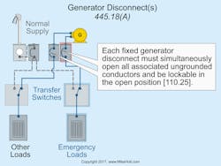
Each fixed generator disconnect must simultaneously open all associated ungrounded conductors and must be lockable in the open position per Sec. 110.25 [445.18(A)], as shown in Fig. 3.
Generators must have provisions to shut down the prime mover; shutdown must comply with all the following [445.18(B)]:
1. Be equipped with provisions to disable all prime mover start control circuits to render the prime mover incapable of starting.
2. Initiate a shutdown mechanism that requires a mechanical reset.
The provisions to shut down the prime mover can satisfy the requirements of Sec. 445.18(A) where the shutdown is capable of being locked in the open position per Sec. 110.25.
Generators with greater than a 15kW rating must be provided with an additional shutdown means located outside the equipment room or generator and comply with Sec. 445.18(B)(1) and (B)(2).
What if generators are installed in parallel? Then the provisions of Sec. 445.18(A) must be capable of isolating the generator output terminals from the paralleling equipment. The disconnecting means is not required to be at the generator [445.18(C)].
Getting it right
One objective of Art. 445 is to correctly select the overprotection for the application. Remember: There are five types of application. Another objective is to correctly size the conductors that contain the overcurrent protection; their ampacity can’t be less than 115% of the nameplate current.
A good installation goes beyond those and other Art. 445 requirements. For example, all wiring is properly labeled, routed, and secured. Additionally, terminations are properly torqued and labeled. These aren’t just nice touches; they’re the hallmarks of a job done right.
Holt is the owner of Mike Holt Enterprises, Inc. in Leesburg, Fla. He can be reached at www.mikeholt.com.
About the Author

Mike Holt
Mike Holt is the owner of Mike Holt Enterprises (www.MikeHolt.com), one of the largest electrical publishers in the United States. He earned a master's degree in the Business Administration Program (MBA) from the University of Miami. He earned his reputation as a National Electrical Code (NEC) expert by working his way up through the electrical trade. Formally a construction editor for two different trade publications, Mike started his career as an apprentice electrician and eventually became a master electrician, an electrical inspector, a contractor, and an educator. Mike has taught more than 1,000 classes on 30 different electrical-related subjects — ranging from alarm installations to exam preparation and voltage drop calculations. He continues to produce seminars, videos, books, and online training for the trade as well as contribute monthly Code content to EC&M magazine.


