The Importance of Contract Documents in an Estimate

Most estimates are prepared from plans and specifications, collectively known as “the contract documents.” These documents should provide the contractor with the necessary information to bid on the project.
Every aspect of a project will be controlled by the contract documents, and the contractor’s work will be judged by them. The contract documents are how the architect and engineer communicate the design to the contractor. The consequences of failing to understand the requirements of the contract are significant.
The “drawings” outline the quantity of work, and the “specifications” clarify the quality of work. The drawings and the specifications should identify and specify every material item and the means of installation.
Early in his or her career, the estimator should have a full understanding of the contract documents. They are binding between an owner and contractor. Every estimator must become familiar with these documents and how to interpret them because the estimate can only be as accurate as the estimator’s interpretation. Risks increase when the estimator fails to properly understand these documents.
When someone refers to the plans and specs, he or she is referring to the drawings and the project manual.
Part 1: Understanding the drawings
The most basic skill in becoming a quality estimator is the ability to read construction drawings. Drawings are filled with symbols, abbreviations, and notes that an estimator must translate into material quantities and/or labor hours. Drawings communicate the desired wishes of the owner and the requirements of the architect.
The architect is the lead designer of the project but does not do all the design work. He is usually assisted by consulting engineers, such as civil, structural, mechanical, plumbing, and electrical. The architect oversees coordination of the consulting engineers and compiles the final set of design drawings.
Most drawings start with a cover sheet that provides general information about the project. There are 11 basic disciplines of drawings.
1. Life Safety — These provide for quick reviews of critical life safety items, including construction type per allowable area, occupant loads, means of egress, fire protection systems, fire department vehicle access, hydrant locations, and more.
2. Phasing — Some projects require portions to be completed in succession. The phasing drawings usually indicate specific areas and their completion date.
3. Landscape — Landscape drawings may include landscape luminaires and site luminaires.
4. Civil — These drawings typically include grading, site utilities, drainage, streets, roadways, and curbs.
5. Structural — Structural drawings provide the estimator with the main structure design. Slab thicknesses, foundation types, and expansion joints are found on these drawings.
6. Demolition — Renovations to existing facilities usually have demolition drawings. They provide areas set for complete demolition and selected removals.
7. Architectural — These plans are prepared by an architect. They typically include floor plans, elevations, and sectional plans. This set will also include finish schedules, door schedules, and architectural details.
8. Mechanical — The architect will employ a consulting engineer to prepare the mechanical drawings. The mechanical drawings sometimes include HVAC and plumbing requirements. They should also include ductwork, air handlers, condensing units, and other equipment associated with climate control of the building.
9. Plumbing — These detail the water lines, plumbing fixtures, sewer lines, and gas lines.
10. Electrical — These typically include the following drawings: site power, site lighting, branch power, lighting, fire alarm, communications, and schedules. They also include a one-line diagram of the power feeders.
11. Telecommunications — Sometimes the electrical engineer will provide a separate set of drawings that include all telecommunications. These drawings include, but are not limited to, data outlets, horizontal cabling, cable trays, and data racks.
Part 2: drawing types
A project’s drawings will not only have a combination of different disciplines, but also different types of drawings. Each drawing type provides important information that will help estimators understand the project. There are four basic types of drawings.
1. Plans — A plan view is a horizontal view looking down from the top of the building. Most projects have more than one plan (e.g., foundation plans, floor plans, and framing plans).
2. Elevations — Elevation drawings show how the building or structure looks from the outside. Typically, all four sides of a building are shown.
3. Sections — Section drawings are used to show key components of the building. These drawings are a close-up view of how the structure is going to be constructed.
4. Details — Details on drawings are a blown-up view of a selected portion of the work. For example, a detail on a drawing may show how the cable tray will be supported. Projects may also have details for the following: luminaire hanging details, utility pole connections, mechanical equipment, and poke-through assemblies.
Part 3: the project manual
The project manual is the second part of the contract documents. The project manual is sometimes referred to as the “specs.” The estimator must understand the conditions of the contract and the effect they have on the bid price.
The estimator will need to do a thorough review of the spec sections that are applicable to the project he or she is bidding.
1. Bidding documents — The bidding documents typically include the following: Advertisement for Bids, Instructions to Bidders, Bid Forms, and the Agreement Form or Contract.
2. General conditions — The general conditions set forth the rules by which the project is constructed and administrated.
3. Supplemental conditions — The supplemental conditions deal with the project’s specific matters related to the contract. Supplemental conditions also modify items in the general conditions.
4. Technical specifications — The technical spec sections will comprise the majority portion of the project manual. The primary purpose of this portion of the specifications is to set forth the following: quality of materials, the standard of workmanship, and methods of installation.
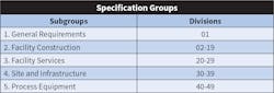
Most construction specifications are arranged by the CSI MasterFormat, as shown in the Table below. The estimator must be familiar with the format and arrangement of the specifications.
Within each division, there are product sections. These are broken into three parts: general, products, and execution. Understanding the products and execution portions is vital. The contractor must install the specified products in the right manner.
Section format descriptions are as follows:
1. General — The “General” heading indicates any related documents, a summary of the items, submittals, and quality assurance. Sometimes it includes the following: abbreviations, definitions, delivery, storage, handling, and warranty requirements.
2. Products — The “Products” heading provides manufacturers and a list of product types, catalog numbers, and specifications for each item.
3. Execution — The “Execution” heading offers installation means and methods. Under this heading, the following are listed: conduit types, minimum sizes and uses, conductor materials and insulations, connection types, mounting heights, and protection.
The drawings and the project manual should specify all materials and installation methods and standards for a project.
The estimator must have the ability to identify portions of the contract documents that are incomplete. When these documents are incomplete, the contractor’s risk will increase. The wise estimator will seek clarification on omissions in the documents prior to bidding on the project.
Remember, the estimator must produce an estimate based on the drawing quantities and products specified in the project manual.
Don Kiper is an independent electrical estimating trainer and consultant based in Niagara Falls, N.Y. He can be reached at [email protected].
About the Author
Don Kiper
Independent Electrical Estimating Consultant
With more than 35 years of experience as a construction electrician, industrial maintenance electrician, foreman, estimator, estimating manager, and project manager, Don has used what he learned to lead in the implementation of estimating software with three electrical contractors where he has worked. Don has 17 years of experience in the construction field and 18 years of office experience and he has personally estimated over $700 million dollars in electrical projects.