Understanding the causes, similarities, and differences between current and voltage distortion will help you pinpoint most power quality problems.
When a writer or speaker mentions harmonic distortion in an article or presentation, they rarely distinguish between current and voltage distortion. This confuses the reader or listener and results in them passing on misinformation. So what's the solution? Only when you truly understand the sources and properties of current and voltage distortion can you acknowledge their differences and realize how each affects a particular portion of the distribution system and the loads powered by that system.
An electrical system supplies power to loads by delivering current at the fundamental frequency. Only fundamental frequency current can provide real power. Current delivered at harmonic frequencies doesn't deliver any real power to the load. When current of a single frequency is present in a system, you can use the measured values in Ohm's Law and power calculations (see Sidebar below). However, when currents of more than one frequency are present, direct addition of the current values leads to a summed value that doesn't correctly represent the total effect of the multiple currents. Instead, you need to add the currents in a manner known as the “root mean square” summation. The equation for the rms addition of currents is as follows:
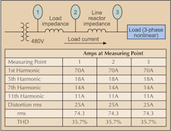
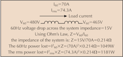
So if a system carries 70A of fundamental current, 18A of 5th harmonic current, 14A of 7th harmonic current, and 11A of 11th harmonic current, the effective current would be 74.3A rms, not the arithmetic sum of 113A. This 74.3A rms value would be the correct value to use in all power calculations.
The same is true for harmonic voltages. To obtain the effective voltage for a system in which voltages of several frequencies are present, you must add the voltages in an rms fashion.
The current THD is the same at each measuring point.
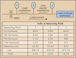
Looking at Fig. 2 again, we see that although the fundamental voltage has dropped from 480V at Point 1 to 465V at Point 3, the increase in harmonic voltage causes the rms voltage to be higher at each measuring point than the fundamental voltage alone. Distortion rms is the rms value of the harmonic voltage with the fundamental left out of the summation, and it increases the farther away you measure from the source. Calculate THD using the same equation used for current distortion.
Effects of current distortion. Since operation of nonlinear loads causes the distorted current, which is path dependent, the effect of current distortion on loads within a facility is minimal. Therefore, harmonic currents can't flow into equipment other than the nonlinear loads that caused them. However, the effect of current distortion on distribution systems can be serious, primarily because of the increased current flowing in the system.All distribution systems are rms current-limited. In a system powering 3-phase loads, for example, a 1,000kVA, 480V transformer is rated to deliver 1,200A rms. But the more harmonic current this transformer has to supply, the less fundamental current it can provide for powering loads. In other words, because the harmonic current doesn't deliver any power, its presence simply uses up system capacity and reduces the number of loads that can be powered.
Harmonic currents also increase I2Z heat losses in transformers and wiring. Since transformer impedance is frequency dependent, increasing with harmonic number, the impedance at the 5th harmonic is five times that of the fundamental frequency. So each ampere of 5th harmonic current causes five times as much heating as an ampere of fundamental current.
In a system powering phase-to-neutral connected loads, detrimental effects are again due to the harmonic currents using up system capacity and reducing the number of useful loads that can be powered. Third harmonic currents cause a further detriment, because they're additive in the neutral conductor. When many computers, which are nonlinear loads, are connected, the neutral current — primarily 3rd harmonic — can be larger than any of the phase currents. These 3rd harmonic currents circulate in the primary (delta) of the distribution transformer that serves the portion of the system powering the computers and are dissipated as heat.
Effects of voltage distortion. Besides overheating, the other major effect of current distortion on an electrical system is the creation of voltage distortion. This distortion will have minimal effect on a distribution system, but unlike current distortion, it isn't path dependent. So harmonic voltages generated in one part of a facility will appear on common buses within that facility. As we see in Fig. 2, high-voltage distortion at the terminals of a nonlinear load doesn't mean high distortion will be present throughout the system. In fact, the voltage distortion becomes lower the closer a bus is located to the service transformer. However, if excessive voltage distortion does exist at the transformer, it can pass through the unit and appear in facilities distant from the origin.The effect on loads within the facility could be detrimental in certain cases. For example, extreme voltage distortion can cause multiple zero crossings for the voltage wave. For equipment where proper sequencing of operations depends on a zero crossing for timing, voltage distortion can cause misoperation. Most modern electrical equipment uses an internal clock for timing sequencing so it's unaffected by multiple zero crossings.
Voltage distortion appears to have little effect on operation of nonlinear loads connected either phase-to-phase or phase-to-neutral.
On the other hand, 5th harmonic voltage distortion can cause serious problems for 3-phase motors. The 5th harmonic is a negative sequence harmonic, and when supplied to an induction motor it produces a negative torque. In other words, it attempts to drive the motor in a reverse direction and slows down its rotation. So the motor draws more 60-Hz current to offset the reverse torque and regain its normal operating speed. The result is overcurrent in the motor, which either causes protective devices to open or the motor to overheat and fail. For this reason, removing 5th harmonic current from systems powering 3-phase loads is often a high priority in industrial facilities.
IEEE 519 “Harmonic Current and Voltage Limits.” This document outlines limits on voltage and current harmonic distortion measured at the point of common coupling (PCC), which is usually defined as the place where the consumer connects to the power supplier. Without going into a thorough analysis, here are several aspects of IEEE 519 that are particularly relevant.IEEE 519 is designed to protect the voltage integrity of the utility grid system, and shouldn't be applied to operations within a particular facility. For example, using the system shown in Fig. 2, the presence of 18.7% voltage distortion at the load does not violate the 5% voltage distortion limit of IEEE 519, since the terminals of the nonlinear load are far removed from the PCC.
Thinking about the possible detrimental effects of a large amount of voltage distortion on this nonlinear load, you have to remember that the load itself causes this distortion. Voltage distortion caused by normal operation isn't detrimental to operation of the load.
In another example, imagine the nonlinear load illustrated in Fig. 1 is an adjustable speed drive (ASD) or a nonlinear load connected to a 1,000kVA, 480V transformer. Current distortion is 25A, or 35.7%, for this drive. But as a percentage of the transformer capacity, the load is negligible. So the effect of powering this drive on the transformer, or on the generation of voltage distortion at the PCC, is insignificant.
Voltage and harmonic distortion levels can vary drastically, depending on the configuration of your system. Your job is to find them, diagnose the cause, and eliminate it before it has a chance to damage your equipment.
Lowenstein is president of Harmonics Ltd., Monroe, Conn.
Before studying the effect of harmonics on an electrical distribution system, you must understand the relationships between current, voltage and impedance. Ohm's Law governs these relationships. This basic electrical tenet states that voltage equals current times resistance. For alternating current (AC) circuits, resistance is replaced by impedance, but the unit of measure (the ohm) remains the same. Using Ohm's Law, you can calculate the voltage losses due to current flow through the impedance of a system. Once you know the impedance, you can find the power dissipated by this current flow.
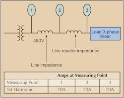
Current measurementFig. A (above) illustrates the principles of current measurement. Laws of physics state that the current into a point must equal the current out of a point. If the current path shown is the only current path, the current measurements at Points 1, 2, and 3 must all be the same. Since the load is linear, all current flows at 60 Hz.
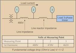
Voltage measurementVoltage measurement is different. Fig. B (below) illustrates the principles of voltage measurement. Measuring in the direction of current flow, the voltage measured at any point is reduced from the voltage measured at a previous point by the product of the current and the impedance (I×Z.) The voltage drop across the system impedance reduces the voltage measured at Point 2. The voltage drop across the relatively high impedance of the line reactor further reduces the voltage measured at Point 3. As you can see, the farther you measure from the source, the more the voltage is lowered.
If the voltage measured at Point 3 is lower than that measured at Point 2, and the current is the same, then some power was lost in the line between the two points. This power is often called the I2Z loss. To ensure that you supply loads with enough voltage for them to operate properly, or to reduce I2Z losses, you must use larger conductor sizes for long electrical runs. This reduces the line impedance and, therefore, the voltage and power losses.
Sidebar: Sample Power Loss CalculationUsing the system shown in Fig. 2 above, it's easy to calculate the power loss due to the voltage drop across system impedance. The data to the right illustrates this calculation. Calculate the power loss for the 60 Hz or fundamental current and then do the same for the rms current. As you can see, the presence of harmonic currents results in increased power losses. In this example, the harmonic currents increase power loss by 132W, or 12.6%. In many cases, removing harmonic currents can result in energy savings.
Measurements on electrical distribution systems powering nonlinear loads usually disclose the presence of both current and voltage harmonics.
