Note: This article is based on the 2020 NEC.
A transformer transfers electrical energy (power) from one system to another by induction, with no physical connection between the two systems (other than grounding and bonding connections). Thus, the National Electrical Code (NEC) refers to transformers as “separately derived systems.”
Most transformers raise or lower voltage, but isolation transformers don’t; they simply decouple the primary winding from the secondary winding.
Some basics
The transformer winding connected to the voltage source is the “primary.” The transformer winding connected to the load is the “secondary.”
The voltage that can be induced in the secondary winding from the primary magnetic field is a function of the number of secondary conductor loops (turns) cut by the primary electromagnetic field. The voltage on the primary side is the “primary line voltage” while the voltage on the secondary side is the “secondary line voltage”.
Transformers are rated in kilovolt-amperes (kVA), where 1kVA = 1,000 volt-amperes (VA).
Delta and Wye
Delta-connected transformers have three windings connected end-to-end. The line conductors connect to each point where two windings meet. This system is called a “Delta” because when it’s drawn out it looks like a triangle (the Greek symbol Delta for the letter D). For a delta/delta transformer, both the primary and secondary windings are delta connected (Fig. 1).
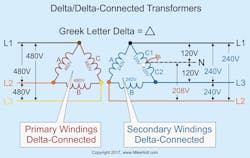
When working with delta transformers, don’t forget about the “high leg” (see the Sidebar at the end of this article).
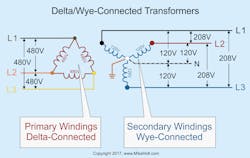
Wye-connected transformers have one lead from each of three windings connected to a common point. The other leads from each of the windings connect to the line conductors. A wye-configured secondary is often represented with a Y-shaped arrangement of the windings (Fig. 2)
Line currents
You can calculate the line current of a transformer by using the appropriate formula for single-phase or 3-phase systems:
Single-phase: I = VA ÷ E
3-phase: I = VA ÷ (E × 1.732)
Overcurrent protection
To protect the windings of a transformer against overcurrent, use the percentages listed in Table 450.3(B) and its applicable notes.
Section 450.3(B) covers the protection of the transformer windings, not the conductors supplying or leaving the transformer.
For currents of 9A or more, Sec. 450.3(B), Note 1 applies. Where 125% of the primary current doesn’t correspond to a standard fuse or nonadjustable circuit breaker, you can use the next higher rating of overcurrent protective device (OCPD), as listed in Sec. 240.6(A).
Primary overcurrent protection, less than 9A example
Question: What’s the maximum primary OCPD rating for a 2kVA continuously loaded, single-phase, 240V transformer?
Primary Current = (Transformer VA Rating) ÷ (Primary Voltage)
Primary Current = 2,000VA ÷ 240V
Primary Current = 8.33A
Primary Protection = (Primary Current) × (Table 450.3(B) Percentage)
Primary Protection = 8.33A × 167%
Primary Protection = 13.92A
Primary overcurrent protection greater than 9A example
Question: What’s the maximum primary OCPD rating for a 45kVA continuously loaded, 3-phase, 480V transformer (Fig. 3)?
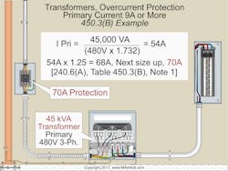
Primary Current = Transformer VA Rating ÷ (Primary Voltage × 1.732)
Primary Current = 45,000VA ÷ (480V × 1.732)
Primary Current = 54A
Primary Protection = (Primary Current) × (Table 450.3(B) Percentage)
Primary Protection = 54A × 125%
Primary Protection = 68A
Thus, use a 70A OCPD in this situation. [Sec. 240.6(A) and Table 450.3(B), Note 1]
Primary conductor sizing
Size the primary conductors at least 125% of the continuous loads, plus 100% of the noncontinuous loads, based on the terminal temperature rating ampacities as listed in Table 310.15(B)(16), before any ampacity adjustment [Sec. 210.19(A)(1)].
Protect conductors against overcurrent per their ampacity after ampacity adjustment, as specified in Sec. 310.15 [240.4]. You can use the next higher standard rating of OCPD (above the ampacity of the conductors being protected) if the OCPD rating doesn’t exceed 800A [Sec. 240.4(B)].
Primary conductor sizing example
Question: What size primary conductor can be used for a 45kVA continuously loaded, 3-phase, 480V transformer, where the primary OCPD is sized at 70A?
Step 1: Size the primary conductor at 125% of the primary current rating.
I = 45,000VA ÷ (480V × 1.732) = 54A
54A × 1.25 = 68A
A 4 AWG conductor is rated 70A at 60°C [Sec. 110.14(C)(1)(a)(1) and Table 310.15(B)(16)].
Step 2: Verify that the conductors are protected per their ampacities [Sec. 240.4].
A 4 AWG conductor rated 70A at 60°C can be protected by a 70A primary OCPD.
Secondary conductor sizing
The ampacity of the secondary conductor must at least equal the rating of the device supplied by the secondary conductors or the OCPD at the termination of the secondary conductors [Sec. 240.21(C)(2)]. Assume the secondary conductors will carry the full capacity of the transformer continuously.
Step 1: Determine the rating of the device supplied by the secondary conductors at 125% of the secondary rating [Sec. 215.2(A)(1)(a)].
Step 2: Size the secondary conductors so they have an ampacity of at least the device rating supplied by the secondary conductors [Sec. 240.21(C)].
Secondary conductor sizing example
Question: What size secondary conductor can be used for a 45kVA continuously loaded, 3-phase, 480V-120/208V transformer?
Step 1: Determine the secondary current rating.
Secondary Current = Transformer VA ÷ (Secondary Voltage × 1.732)
I = 45,000VA ÷ (208V × 1.732)
I = 125A
Step 2: Size the secondary OCPD for continuous loading (125% of the secondary current rating) [Sec. 215.3].
125A × 1.25 = 156A
Thus, use a 175A OCPD in this situation [Sec. 240.6(A)].
Step 3: Size the secondary conductor so it has an ampacity of at least the 175A secondary OCPD (Step 2) [Sec. 240.21(C)(2)].
Use a 2/0 AWG rated 175A at 75°C [Sec. 110.14(C)(1)(b) and Table 310.15(B)(16)]
Grounding and bonding
A system bonding jumper, sized per Sec. 250.102(C) based on the area of the secondary conductors [Sec. 250.30(A)(1) and Sec. 250.28(D)(1)], must be installed at the same location where the grounding electrode conductor terminates to the neutral point of a transformer [Sec. 250.102(C)].
A grounding electrode conductor must connect the neutral point of a separately derived system to a grounding electrode of a type identified in Sec. 250.30(A)(4). Size the grounding electrode conductor per Sec. 250.66, based on the area of the ungrounded secondary conductor [Sec. 250.30(A)(5)].
Avoiding errors
A calculation error can have tragic results. So how can you reduce the chances of error in your transformer calculations?
The math involved isn’t particularly challenging, but if you select the wrong formula, your results will be wrong even if your math is right. These four simple steps will help ensure you select the correct formula for a given application:
- Double-check the VA rating.
- Identify the primary and secondary voltages, and if single-phase or 3-phase.
- Double-check your load characterization and calculations.
- Check that you used the correct formulas. Here’s a tip to help you do that without your eyes glazing over: Reference the wrong formulas. For example, you’re working in a single-phase system. Look at the formula for a 3-phase one. Is this what you used? If not, great. Move on to the next item, and use a similar process.
These materials are provided to us by Mike Holt Enterprises in Leesburg, Fla. To view Code training materials offered by this company, visit www.mikeholt.com/code.

About the Author

Mike Holt
Mike Holt is the owner of Mike Holt Enterprises (www.MikeHolt.com), one of the largest electrical publishers in the United States. He earned a master's degree in the Business Administration Program (MBA) from the University of Miami. He earned his reputation as a National Electrical Code (NEC) expert by working his way up through the electrical trade. Formally a construction editor for two different trade publications, Mike started his career as an apprentice electrician and eventually became a master electrician, an electrical inspector, a contractor, and an educator. Mike has taught more than 1,000 classes on 30 different electrical-related subjects — ranging from alarm installations to exam preparation and voltage drop calculations. He continues to produce seminars, videos, books, and online training for the trade as well as contribute monthly Code content to EC&M magazine.