The Differences Between Grounding and Bonding – Part 12 of 12

Courtesy of www.MikeHolt.com.
This article is the last in a 12-part series on the differences between grounding and bonding. It is based on 2020 NEC requirements.
These three Chapter 8 Articles have significant implications for the grounding and bonding of communications systems:
- Article 800 [General Requirements for Communications Systems] covers general requirements for installing communications circuits, community antenna television and radio distribution systems, network-powered broadband communications systems, and premises-powered broadband communications systems, unless modified by Art. 805 [Communication Circuits] or Art. 820 [CATV and Coaxial Cable].
- Article 810 [Radio and Television Equipment] covers antenna systems for radio and television receiving equipment, amateur radio transmitting and receiving equipment, and certain features of transmitter safety. It also includes antennas such as multi‑element, vertical rod and dish, and the wiring and cabling connecting them to the equipment.
- Article 820 [Community Antenna Television (CATV) and Radio Distribution Systems (Coaxial Cable)] covers the installation of coaxial cables to distribute limited‑energy high‑frequency signals for television, cable TV, and closed‑circuit television (CCTV). CCTV is often used for security purposes.
Article 800
Bonding conductors and grounding electrode conductors must be:
- Listed and permitted to be insulated, covered, or bare [Sec. 800.100(A)(1)].
- Copper or other corrosion‑resistant conductive material, stranded or solid [Sec. 800.100(A)(2)].
- At least 14 AWG with a current‑carrying capacity of at least that of the grounded metallic sheath member(s) or protected conductor(s) of the communications cable or coaxial cable and doesn’t have to be larger than 6 AWG [Sec. 800.100(A)(3)].
- As short as practicable [Sec. 800.100(A)(4)]. For one‑ and two‑family dwellings, the bonding conductor or grounding electrode conductor can’t exceed 20 ft in length. Exception: If the bonding conductor or grounding electrode conductor is more than 20 ft long for one‑ and two‑family dwellings, a separate ground rod at least 5 ft long [Sec. 800.100(B)(3)(3)] with fittings suitable for the application [Sec. 800.100(C)] must be installed. The additional ground rod must be bonded to the power grounding electrode system with a minimum 6 AWG bonding jumper [Sec. 800.100(D)] (Fig. 1).
- Run in as straight a line as practicable [Sec. 800.100(A)(5)].
- Protected so as not to be subject to physical damage [Sec. 800.100(A)(6)]. If installed in a metal raceway, both ends of the raceway must be bonded to the contained conductor or connected to the same terminal or electrode to which the bonding conductor is connected.

The bonding conductor must be connected per Sec. 800.100(B)(1), (B)(2), or (B)(3):
(1) Buildings with an Intersystem Bonding Termination. The bonding conductor must terminate to the intersystem bonding termination as required by Sec. 250.94.
(2) Building Without Intersystem Bonding Termination. The bonding conductor or grounding electrode conductor must terminate to the nearest accessible location of one of the seven items enumerated in (B)(2). For example, it can terminate to the service disconnect enclosure (but never on a door or in a way that interferes with a door).
(3) In Buildings Without Intersystem Bonding Termination or Grounding Means. If the building has no intersystem bonding termination, connect the grounding electrode conductor to one of the three items enumerated in (B)(3). For example, you can connect it to an individual grounding electrode described in Sec. 250.52(A)(5), (A)(7), and (A)(8) [Sec. 800.100(B)(3)(2)].
Connections to grounding electrodes must comply with Sec. 250.70 [Sec. 800.100(C)].
Terminations at the grounding electrode must be by exothermic welding, listed lugs, listed pressure connectors, or listed clamps. No more than one conductor can terminate on a single clamp or fitting unless the clamp or fitting is listed for multiple connections. Grounding fittings that are concrete‑encased or buried in the earth must be listed for direct burial.
If a separate grounding electrode (such as a rod) is installed for a communications system, it must be bonded to the building’s power grounding electrode system with a minimum 6 AWG copper conductor [Sec. 800.100(D)].
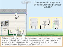
Where bonding or grounding is required, devices used to connect a shield, sheath, or noncurrent-carrying metallic members of a cable to a bonding conductor or grounding electrode conductor must be listed or be part of listed equipment [800.180] (Fig. 2).
Article 810
Unlike other Articles in this chapter, Art. 810 is not covered by the general rules in Art. 800. So it stands alone in the NEC unless a rule in Art. 810 references a specific rule elsewhere in the Code.
Outdoor masts and metal structures that support antennas must be bonded per Sec. 810.21 unless the antenna and its related supporting mast or structure are within a zone of protection defined by a 150-ft radius rolling sphere [Sec. 810.15].
Informational Note. See NFPA 780-2017 Standard of Lightning Protection Systems regarding the term rolling sphere.
Each lead-in conductor from an outdoor antenna must be provided with a listed antenna discharge unit [Sec. 810.20(A)]. Locate the antenna discharge unit as near as practicable to the point of entrance (inside or outside doesn’t matter), but not near combustible material or in a hazardous (classified) location as defined in Art. 500 [Sec. 810.20(B)]. The antenna discharge unit must be bonded or grounded per Sec. 810.21 [Sec. 810.20(C)].
Bonding conductors and grounding electrode conductors must meet the requirements of Sec. 810.21(A) through (K). These include things you would expect, such as they must be run in a straight line and physically protected. They also include things that are not so obvious, such as the fact these conductors do not have to be insulated.
Grounding the lead-in antenna cables and the mast helps prevent voltage surges caused by static discharge or nearby lightning strikes from reaching the center conductor of the lead-in coaxial cable. Because the satellite dish sits outdoors, wind creates a static charge on the antenna and on the cable to which it is attached. This charge can build up until it jumps across an air space, often passing through the electronics inside the low noise block down converter feedhorn (LNBF) or receiver.
In addition to complying with Part III of Art. 810, antenna systems for amateur (ham) and citizen band transmission and receiving stations must comply with Sec. 810.11 and Sec. 810.15.
Each conductor of a lead-in for outdoor antennas must be provided with an antenna discharge unit or other suitable means to drain static charges from the antenna system [Sec. 810.57]. But an antenna discharge unit or other suitable means is not required where the:
- Lead-in is protected by a continuous metallic shield that is grounded with a conductor per Sec. 810.58 [Exception No. 1].
- Antenna is grounded with a conductor per Sec. 810.58 [Exception No. 2].
Bonding conductors and grounding electrode conductors for these radios must comply with Sec. 810.58(A) through (C):
(A) Other Sections. All bonding conductors and grounding electrode conductors for amateur and citizen band transmitting and receiving stations must comply with Sec. 810.21(A) through (C) (corrosion-resistant material, insulation not required, securely fastened in place).
(B) Size of Protective Bonding Conductor or Grounding Electrode Conductor. The protective bonding conductor or grounding electrode conductor for transmitting stations must be as large as the lead-in and at least 10 AWG copper, bronze, or copper-clad steel.
(C) Size of Operating Bonding Conductor or Grounding Electrode Conductor. The operating bonding conductor or grounding electrode conductor for transmitting stations must be at least 14 AWG copper or its equivalent.
Article 820
Coaxial cables supplied to a building must have the outer conductive shield bonded or grounded as close as practicable to the point of entrance per 820.100 [820.93(A)] (Fig. 3).
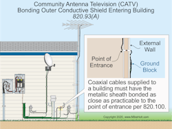
Pick a grounding block location that helps keep the bonding or grounding electrode conductor as short as practicable.
The outer conductive shield of a coaxial cable must be bonded or grounded per Sec. 800.100(A) and (B).
Exception: For systems using coaxial cable completely contained within the building (i.e., they do not exit the building) and isolated from outside cable systems, the shield can be bonded by a connection to an equipment grounding conductor as described in Sec. 250.118. This connection can be made through a grounded receptacle using a dedicated bonding jumper and a permanently connected listed device. You cannot use a cord and plug for the connection to an equipment grounding conductor.
The crux of the matter
When a communications system uses an outdoor antenna, you have another path that can carry undesired current. Static buildup from just the wind can result in a dangerous discharge. By eliminating differences of potential around the antenna system, you can prevent such a discharge. One benefit is this protects the input and signal processing stages of the equipment. But a more important benefit is it reduces the risk of fire or electrocution.
These materials are provided to us by Mike Holt Enterprises in Leesburg, Fla. To view Code training materials offered by this company, visit www.mikeholt.com/code.

About the Author

Mike Holt
Mike Holt is the owner of Mike Holt Enterprises (www.MikeHolt.com), one of the largest electrical publishers in the United States. He earned a master's degree in the Business Administration Program (MBA) from the University of Miami. He earned his reputation as a National Electrical Code (NEC) expert by working his way up through the electrical trade. Formally a construction editor for two different trade publications, Mike started his career as an apprentice electrician and eventually became a master electrician, an electrical inspector, a contractor, and an educator. Mike has taught more than 1,000 classes on 30 different electrical-related subjects — ranging from alarm installations to exam preparation and voltage drop calculations. He continues to produce seminars, videos, books, and online training for the trade as well as contribute monthly Code content to EC&M magazine.