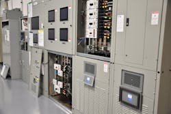
One of the most dangerous locations in a power distribution system with regard to incident energy is that first panelboard on the secondary of a transformer. With some thought in your design — even if it’s an existing design — it is possible to address this safety concern by moving the hazard into an area that is less likely to require justified energized work.
Understanding the hazard
When evaluating the incident energy at a fault location in the system, the interrupting time of the protective device upstream from the point of the fault is used to determine incident energy. An arc fault could occur in various locations within equipment, including the line side or load side of the main overcurrent protective device in a panelboard. In addition to a fault occurring on the line side of the main overcurrent protective device (OCPD), the other concern is line-side propagation of the fault. You can get an escalation of the arcing fault to the line-side of the main OCPD because of the conductive plasma cloud. When the integral main overcurrent protective device is not adequately isolated from the bus, the upstream protective device must be considered as protecting the main and bus.
The next upstream OCPD for this load-side panelboard of a transformer is on the primary side of the transformer. The primary OCPD of a transformer has influences that make it such that it doesn’t provide adequate protection for the secondary side distribution equipment. The size of the primary OCPD is driven by a few key factors:
1. Section 450.3 of the National Electrical Code (NEC)
This Section advises the maximum size OCPD for the primary of the transformer. It does NOT govern the smallest size OCPD that can be used.
2. Selective coordination
Although the first OCPD on the secondary of the transformer does not need to coordinate with the primary OCPD, the secondary branch and feeder devices in the panel do to achieve selectivity. This can drive the primary OCPD upward in ampere size closer toward the maximum limits as defined by Sec. 450.3 of the NEC.
3. Transformer inrush current
The primary OCPD must permit the transformer to energize, which means it must permit the inrush currents to flow without tripping. Inrush currents could be anywhere from six to 10 times the full load ampere (FLA) rating. Staying away from inrush current will drive the instantaneous pickup to a higher value for a circuit breaker and (in the case of the fuse) require a larger fuse size. In addition, for circuit breakers, the short-time delay settings (if present) would be increased in time as inrush currents on a transformer can persist for as long as 0.1 sec. Times vary, so you should always take the worst-case scenario.
These factors play a role in increased incident energy values for that first panelboard on the secondary of the transformer as intentional delays are put in place related to the special characteristics of the transformer.
Design considerations
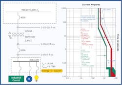
Figure 1 illustrates the transformer protection scheme selected for a 225kVA transformer that does not require selective coordination. The primary OCPD is 400A with a 400A feeder supplying the transformer. The secondary includes a 600A panelboard.
The incident energy for the first panelboard on the secondary of this 225kVA transformer is 32.5 Cal/cm2. The "2 second rule," provided as part of IEEE 1584, is used as the arcing current is in the long-time region of the upstream 400A feeder circuit breaker. Some small design changes can be made to increase safety for this application. Two concepts to reduce incident energy at the secondary include:
1. Relocate secondary main.
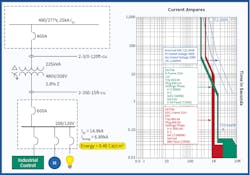
Moving the main OCPD out of the panelboard on the secondary of the transformer and including it in its own enclosure feeding a main lug only panel would enable the incident energy of the panelboard to be based on the secondary OCPD instead of the primary OCPD. This would result in a considerable decrease in incident energy.
Although the single-line diagram in Fig. 2 has changed with the relocation of the main breaker, the trip curves remain the same for the circuit breakers in both design configurations. This effectively moves the high incident energy into the secondary disconnect, which could be a breaker in a box or a fusible disconnect switch.
This design has effectively moved the high incident energy into an area of the power system that will not be accessed as frequently as the panelboard, which includes all the feeder and/or branch overcurrent protective devices. If thought of ahead of time, the engineer can specify a transformer with an integrated secondary circuit breaker. This would reduce the labor costs associated with the installation.
2. Install an arc reduction maintenance switch.
The value of an arc reduction maintenance switch (ARMS) is that it can be turned on and off. This allows the electrical worker to reduce the level of incident energy when justified energized work must be performed.
This option can be used on the primary side of the transformer in the circuit breaker or fusible switch feeding this transformer. The maintenance switch puts in place an instantaneous trip at a much lower value than normal and if lower than the arcing current significantly reduces the clearing time. This is appropriate for the line side of the transformer as once the transformer is energized inrush currents are no longer a concern.
The disadvantage that this design has over the first option noted above is that moving the main OCPD out of the secondary panelboard provides a continuously reduced incident energy for the panelboard. The ARMS would only provide arc reduction when it is engaged by the electrical worker.
Review and compare the TCC curves of Fig. 1 and Fig. 3 to see the difference that the ARMS provides.
Leveraging the option to address the situation of high incident energy at that first piece of equipment on the secondary side of a transformer by providing an ARMS on the primary feeder overcurrent protective device to that transformer or at the secondary switch or enclosed circuit breaker identified above as the first option can prove to be quite effective. Remember the fact that we size that primary OCPD to accommodate the transformer inrush current and to meet selective coordination needs. This may cause us to increase the size of the primary OCPD as high as permitted by the NEC, which is 250%. Typically, we size it around 125% of the primary full load amps. Even at 125%, this increase in size ensures the inrush current of the transformer doesn’t trip the primary OCPD when energized. Equipping the primary circuit breaker or fusible switch with a solution that adjusts the response time of the breaker on demand when justified energized work is being conducted downstream can significantly reduce the incident energy at that secondary piece of equipment.
Technology solutions like an ARMS are recognized as an effective arc reduction technology in Sec. 240.87 of the NEC. Turning this technology on will lower the instantaneous override settings of the primary circuit breaker, provide an indication light to let the electrical worker know it is turned on, and facilitate the ability of that circuit breaker to respond to downstream arcing currents. This provides an effective means to increase safety for the electrical worker.
Conclusions
The bottom line is an engineer can make decisions in the design phase of a project that will reduce an electrical worker’s exposure to incident energy. One of the areas with the highest incident energy is that first panelboard on the secondary of the transformer. By simply moving the main OCPD out of the first panel downstream of the transformer to its own enclosure and including an ARMS switch on the feeder OCPD to the transformer, an engineer can help protect electrical workers through the concept of safety by design. Integrating the secondary circuit breaker with the transformer would reduce installation time and costs as well as provide a safer worker environment.
Domitrovich is vice president, technical sales for Eaton. He can be reached at [email protected].
About the Author
Thomas Domitrovich
National Application Engineer
Domitrovich is an Electrical Engineer within Eaton’s electrical group with experience in engineering, sales & marketing, business development and product management. He is actively involved with various electrical industry organizations and most recently focuses on the continued growth of electrical safety. Domitrovich is an author with a wide range of trade magazine articles including columns in two industry trade magazines focused on electrical safety. He sits on NFPA Code Making Panel 2 for the continued development of the National Electrical Code (NFPA 70). He is also on the NFPA committee for the continued development of NFPA 73 and chairs various committees for other electrical industry organizations. Domitrovich is a LEED Accredited Professional, a licensed Professional Engineer and holds a Bachelor of Electrical Engineering from Gannon University.
