Beyond the Utility Grid: The Rise of Transit Microgrids
Key Takeaways
- Early utility coordination is essential to ensure compliance with interconnection requirements and optimize system design for renewable capacity, protection, and operational modes.
- PV systems can be canopy-mounted, floating on water, or integrated into structural elements to maximize land use and efficiency while supporting sustainability goals.
- Battery energy storage systems support load management, peak shaving, and emergency resilience, but must adhere to strict fire safety and installation codes.
- Engine generators provide dispatchable power, balancing renewable variability and ensuring reliable backup, with considerations for fuel type and environmental impact.
- EV charging infrastructure, including ground-mounted, overhead, pantograph, and wireless systems, enhances fleet operations and can participate in V2G services for grid support.
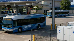
The days when the electric utility was the sole provider of electrical energy for a transit facility are in the past. Multiple sources of electrical energy are now being interconnected to enhance power system resiliency and reduce electricity costs. This article focuses on important considerations for designing these interconnected electrical power sources found at bus and other transit facilities. For definitions of key technologies and operating modes discussed throughout this article, see the Sidebar below on “Important Terms to Know.”
Before selecting equipment or defining operating modes, the electrical design team must establish how the system will interact with the serving utility. Let’s take a look at how that process works.
Electric utility coordination and interconnection requirements
Early coordination with the electric utility is essential when designing a microgrid. The design team should begin by reviewing the electric utility’s published interconnection requirements and meeting with an electric utility representative to confirm how those requirements apply to the project’s generation sources, load profile, and operating strategy.
Electric utility requirements vary by service territory, but they commonly influence major design decisions, including:
- Renewable generation capacity: Limits or conditions on the amount of PV, battery storage, or other distributed energy resources (DERs) that may be interconnected.
- Protective relaying: Requirements for protection, control, and isolation equipment that allow the microgrid to operate safely in conjunction with the electric utility system.
- System configuration: Electric utility preferences for how equipment is arranged, monitored, and controlled at the point of interconnection.
- Operating modes: Expectations for how the microgrid transitions between grid‑connected and islanded operation during outages or disturbances.
Together, these requirements shape the microgrid architecture, the facility electrical distribution system, and the sequence of operations used to coordinate normal, emergency, and island modes.
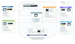
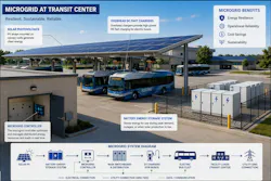
A transit‑based microgrid system consists of various DERs connected with transit facility loads. Loads unique to transit facilities that can benefit from connection to a microgrid include EV bus and customer vehicle charging infrastructure, rail system power, and general building and site lighting loads (see the Figure).
Typical distributed energy resources and considerations
Some of the common DERs found in transit microgrids include photovoltaic (PV) systems, BESSs, and engine generators.
PV systems
PV systems are a common power generation resource in microgrid electrical distribution systems. When integrated into a microgrid, PV systems provide scalable, localized power that supports grid resilience and sustainability. Article 690 of the National Electrical Code (NEC) governs the installation of PV systems with generating capacities up to 5 megawatts (MW). For large-scale PV electric supply stations rated 5MW or greater that are not under exclusive electric utility control, Art. 691 of the NEC governs the installation.
Modern microgrid architecture maximizes infrastructure efficiency by using innovative structural systems, such as canopy‑mounted solar panels that transform standard parking lots, customer waiting platforms, and pedestrian walkways into dual-use structures. In these applications, solar arrays either sit directly over the canopy structures or are integrated into the structural components.
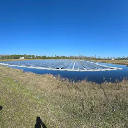
To mitigate land use constraints, microgrids increasingly incorporate floating photovoltaics (FPV), in which solar arrays are deployed on underutilized natural or human-made bodies of water (Photo 1). In addition to reducing land disturbance, this application allows the water to provide a natural cooling effect that improves solar panel conversion efficiency. The floating arrays also help reduce water evaporation and algae growth. Common FPV applications in transit and transportation settings include dockside power for ferries in protected harbors, toll plaza power, and roadway signage power.
Battery energy storage systems (BESSs)
These systems are commonly used in microgrid electrical distribution systems along with an energy production source, such as a PV system, to store energy, support load management, and improve system resilience.
A BESS is typically installed at bus depots to capture and store electricity during off-peak hours or from on-site renewable sources, such as PV arrays. This setup benefits the transit facility by performing peak shaving — the discharge of stored power to support electric bus charging during high‑demand periods, which prevents strain on the local electrical grid and avoids expensive electric utility demand charges.
BESS deployments must comply with applicable fire, building, and electrical codes, including NFPA 855, Standard for the Installation of Stationary Energy Storage Systems, the International Fire Code, and Art. 706 of the National Electrical Code (NFPA 70). These requirements address equipment location, unit capacity, fire protection, ventilation, and separation distances to reduce thermal runaway risks.
Indoor BESS installations are generally prohibited in critical habitable buildings and below-grade areas unless proper ventilation and emergency power-off systems are provided. These systems typically require a dedicated, fire-rated utility room with direct exterior wall access to support ventilation and smoke control.
Outdoor BESS containers must maintain required setbacks from lot lines, public ways, and building openings such as doors, windows, and fresh air intakes. Typical clearances range from 10 to 25 feet, although reduced distances may be permitted when manufacturer fire-testing reports demonstrate that thermal runaway will not propagate to nearby exposures.
Rooftop BESS installations must satisfy structural load requirements and address fire safety risks. They are often restricted on combustible roof decks and must be located so they do not obstruct ventilation, exhaust, or rooftop access pathways.
Individual cabinets and racks should be separated to help prevent fire spread between units. Where required setbacks from buildings or property lines cannot be met, exterior walls may require fire-rated construction, such as 1- or 2‑hour fire barriers, to protect adjacent exposures.
Distributed energy resource inverters
PV systems and BESSs operate using direct current (DC) input supply current, whereas electric utility systems operate using alternating current (AC) input supply current. Inverters convert DC to AC to allow for the interconnection of PV and BESS-supplied power with the microgrid power distribution system.
Modern microgrid PV systems use advanced smart inverters to actively manage both real power (watts) and reactive power (volt-amperes reactive). Unlike older inverters that simply push power into the system, modern inverters can both supply and absorb power as needed. This dynamic capability allows them to continuously adjust voltage and frequency, acting as the backbone of microgrid stability through the following essential functions:
- Voltage regulation: Inverters automatically inject or absorb reactive power to stabilize localized voltage swings, preventing overvoltage or undervoltage.
- Frequency support: Dynamic active power curtailment or ramping mimics the inertia of traditional mechanical generators to counter frequency deviations.
- Black-start capability: Grid-forming controls allow the inverter to establish a local voltage and frequency reference, effectively jump-starting a microgrid during absolute utility outages.
- Power quality optimization: Advanced active filtering algorithms dampen harmonics and correct phase imbalances caused by nonlinear loads within the microgrid. Smart inverter technology can support power factor correction by generating or absorbing reactive power.
Engine generators
Selecting generators for a microgrid application requires balancing baseload demands with the variable output of renewable sources. Key factors include dispatchability, ramp rate, fuel availability, and grid‑forming capability. The generator must also operate efficiently at partial loads to minimize fuel consumption and emissions. The electrical installation of backup power generators is governed by NFPA 37, Standard for the Installation and Use of Stationary Combustion Engines and Gas Turbines; NFPA 110, Standard for Emergency and Standby Power Systems; and Art. 445 of the NEC (NFPA 70).
Generators act as the backbone of a microgrid when disconnected from the main utility. A generator operating in isochronous mode is essential to establishing the microgrid’s voltage and frequency references, while grid-following generators — typically operating in droop control mode — supply active and reactive power alongside existing renewable resources.
Traditional fossil-fuel generators suffer from poor efficiency and increased maintenance when operated below certain thresholds (typically 30% to 40%). Selecting appropriately sized generators or incorporating an energy storage system prevents degradation caused by light-load operations.
Fast-acting generators are required to handle sudden load step changes and the intermittency of renewable energy (e.g., solar or wind). Combined heat and power units, natural gas linear generators, or advanced diesel sets are often selected to balance rapid frequency regulation with continuous output.
Microgrids often employ diverse generation to ensure long‑term energy security. Selecting units that can accommodate dual fuels (e.g., diesel/locally sourced biofuels) significantly reduces carbon footprints and operational costs.
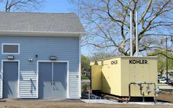
Natural gas generators do not require on-site fuel storage, reducing maintenance and staff labor (Photo 2). They produce fewer emissions but require a reliable natural gas supply. If the area is prone to natural disasters or utility pipeline disruptions, the authority having jurisdiction (AHJ) may not approve natural gas generators for critical emergency applications.
Diesel generators are suitable for instantaneous power surge loads, such as motors. The engines can start reliably in extremely cold weather, making them the standard for critical backup applications. They require on-site fuel storage via subbase or underground tanks. Facilities must incorporate strict spill containment measures and manage fuel degradation over time.
Electric vehicle charging in transit microgrids
EV charging is one of the most significant electrical loads at many transit facilities and can be an important part of a transit microgrid strategy. At bus facilities, EV charging systems may also support vehicle-to-grid (V2G) functionality, which allows energy stored in plugged-in electric buses to be discharged back into the microgrid during periods of high utility demand, constrained generation, or emergency operation.
This section summarizes common EV charging installation approaches used to support transit bus fleets and explains how those systems can contribute to microgrid performance, operational flexibility, and energy resilience.
Ground-mounted chargers
At bus depots where public access is controlled or restricted, ground-mounted DC fast chargers are commonly used. This installation type is the easiest and most economical to install. Similar to the typical fuel dispenser setup, ground-mounted EV charging dispensers are located where buses can dock in parallel alongside them for charging. The dispensers are typically wired to the larger power distribution system via a power converter.
This installation approach may obstruct vehicle passage. Additionally, it may require significant trenching to install underground ducts and concrete support pedestals for dispensers.
Overhead- or column-mounted chargers
At transit centers where passengers board buses, as well as at large bus depots, overhead- and/or wall‑mounted EV charging installations are a common installation configuration. These installation setups typically relocate the bus charging infrastructure out of the range of pedestrian access, making the installation more resistant to tampering. Thought must be put into how the dispenser cables will be routed and stored for bus charging while being protected from theft or damage.
Conduits may be routed above grade for this installation setup, leading to faster installation and reduced costs. In bus depot installations, overhead mounting reduces obstructions within drive aisles, contributing to safer bus operations.
Pantograph chargers
A pantograph EV charger is a structure that automatically uses a mechanical means of attaching and detaching the EV bus from the charging infrastructure. Usually, the charging occurs on top of the bus roof. Attachment can be through a mast-mounted motorized arm that lowers toward the bus roof and connects with contact rails or by a pantograph mounted to the bus with a robotic arm that extends upward to attach the bus to the charging infrastructure.
This installation type has rapid charging capability (also called opportunity charging). With pantographs being able to flash charge buses and deliver 450 to 600kW of power in 3 to 6 minutes, pantograph charging infrastructure allows bus routes to be extended and charging to occur away from centrally located bus depots. The automated charge connection process creates less manual work for bus drivers.
Wireless bus charging
Wireless bus charging is a modern and sleek charging configuration in which the charging unit is generally mounted in the ground, allowing buses to park over the unit to charge wirelessly through inductive power transfer (IPT) technology (Photo 3).
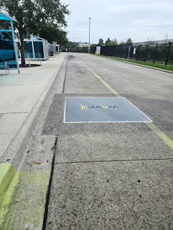
This installation type automates the connection process for charging, eliminating the need for drivers to manually handle heavy cables to charge the bus. When compared to the pantograph method, there are no moving mechanical parts, leading to a reduction in maintenance. However, wireless charging systems have several disadvantages. IPT technology has a larger upfront cost than other charging alternatives and generally operates at lower efficiency than direct bus plug‑in charging technology. Wireless systems also have slower charging rates and may require additional maintenance because the charging technology is embedded within the roadway.
The role of electric vehicle chargers in the microgrid
When used in conjunction with DERs in a microgrid configuration, EV charging infrastructure offers substantial flexibility to a bus agency (Photo 4). The microgrid, when coordinated with the EV charger’s charge management system, can be configured to charge energy storage systems at various points throughout the day. The system can also use PV systems and BESSs to perform peak shaving, reducing utility service charges.
From an energy resilience perspective, coupling a microgrid containing energy storage with an EV bus fleet provides reliability during regional power disturbances, allowing fleet operations to continue. Depending on user preference, the charge management system can reduce or stop fleet charging and can divert power usage to facilities or to charging, offering flexibility for business resilience teams managing operations.
The fleet itself is a large energy storage apparatus. If configured in V2G mode, the fleet can power facilities and infrastructure, enhancing system reliability.
In summary
Microgrid design for transit systems integrates DERs to enhance resilience and efficiency, focusing on PV systems, BESSs, and EV charging infrastructure. The approach should address utility requirements and operational modes to optimize transit facility energy use. Key components include:
- PV systems, typically with canopy-mounted configurations, BESSs adhering to strict fire and safety codes, and engine generators balancing renewable output and fuel diversity.
- EV charging technologies, such as ground-mounted, overhead- or column-mounted, pantograph, and wireless inductive charging, are incorporated for fleet operations and customer vehicles. When integrated with a microgrid, these systems enable peak shaving and enhance energy resilience.
- The design of such a system should emphasize compliance with the NEC and other relevant design standards, site-specific installation constraints, and microgrid control architectures for seamless grid-connected and islanded operation.
Important Terms to Know
Battery energy storage system (BESS): A system that captures electrical energy from the grid or renewable systems and stores the energy in rechargeable batteries for later use. It helps stabilize power grids, manage peak energy demand, and provide reliable backup power.
Distributed energy resource (DER): Small-scale, decentralized energy generation and storage technologies located close to the point of usage. They allow users to generate, store, and manage their own electricity directly on the local distribution grid.
Island operation: A mode in which a localized energy network disconnects from the main utility grid and functions autonomously. It uses its own on-site power sources, like solar arrays, batteries, generators, or other DERs to continuously supply electricity to local loads.
Inverter: An electronic device that converts direct current (DC) electricity — such as the power from a battery or solar panel — into alternating current (AC) electricity.
Microgrid: A localized, self-contained power network that generates, stores, and manages its own electricity for a specific area. It can operate seamlessly while connected to the main utility grid or as a stand‑alone system during power outages.
Pantograph for electric vehicles (EVs): An automated, overhead charging system that uses a motorized arm to connect stationary chargers to conductive rails on the roof of the vehicle. It enables rapid, high-power DC charging of electric buses and heavy-duty fleets during operational stops without requiring manual plug-in cables.
Photovoltaic (PV): The technology and process of converting sunlight directly into electricity. It relies on semiconductor materials to generate an electric current when sunlight is incident upon the unit equipment.
About the Author
Orlando Cruz, PE
Orlando Cruz, PE, Senior Electrical Engineer, CDM Smith, is a senior electrical engineer with experience supporting complex power systems projects worldwide. His work focuses on electrical consulting for resilient power infrastructure, including design considerations for advanced distribution systems and transit-related energy applications.
Supasit Jong, PE
Supasit Jong, PE, Senior Electrical Engineer, CDM Smith, is a senior electrical engineer at CDM Smith with more than 25 years of experience in designing consulting and analyzing electrical power distribution systems.