The Case of the Exploding Capacitor

By their very nature, power factor correction capacitors are special devices that operate close to their dielectric breakdown limits — time, temperature, and peak voltage, all of which contribute to such a failure. This is the story of one such catastrophic occurrence that unfortunately resulted in a serious injury to a plant maintenance worker.
Setting the stage
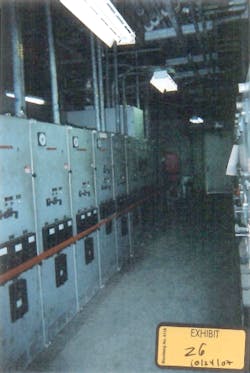
At a large aluminum ore processing plant on an island in the Caribbean, the electrical loads were so large that an on-site, coal-fired steam generator provided primary power for the facility. Multiple large motor loads ranging from 480V to 4,160V existed. The focus of this article will be on a 4,160V blower motor for a cooling fan in the generator building — the control for this load was located in the 4,160V switchgear building (Photo 1).
The accident
After entering the switchgear room and starting the fan motor from the motor control center (MCC), the plant operator heard a strange noise. Searching to investigate the source of the disturbance, he quickly determined the unusual sound seemed to be coming from behind the MCC. As he entered this area (putting him approximately 4 feet to 5 feet from the cabinet), an explosion occurred — causing the victim to receive a serious arc flash injury that included burns to his hands, arms, and face.
Initial investigation
After the accident, engineers investigating the incident found an exploded 4,160V, 125kVA capacitor. Because the capacitor was oil-filled, it produced a fireball upon explosion. The capacitor bank was located in an enclosed shelf unit with heavy-gauge steel perforated exterior walls. One area of the wall had been exploded outward at the capacitor location (Photo 2). The accident capacitor, which was 20 years old at the time of the explosion, was one of two paralleled to the motor feeder. When the victim investigated the source of the noise, he was unknowingly staring into the face of ground zero. Although he did have safety glasses on, he was not wearing any other personal protective equipment (PPE) at the time of the accident.
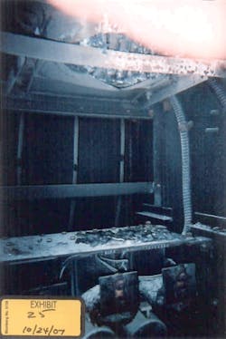

Investigators did not indicate the cause for failure; however, they stated dust and the salt atmosphere could have contributed to the failure. Interestingly, no recommendations were made to test the adjacent capacitor, replace it, or do a thermal scan of all similar devices. Obviously, the adjacent capacitor suffered from the explosion (Photo 3). Some blame was assigned to the porous cabinet, which investigators alleged had contributed to the accident by allowing the fireball to escape. The cabinet was arc flash rated but not fault current rated. No recommendation for redesign was made, nor was there any mention of a dielectric breakdown.
Subsequent investigation by plant personnel indicated the likely culprit in this case was the fact that the cabinet was not designed to protect against electrical oil fireball flash hazards, and “adequate overcurrent protection” was lacking. As a result, the proximate cause was deemed a “defective capacitor.”
Author’s involvement
After being contacted by a local attorney, my official start on this case began with a letter from the plaintiff’s attorney, describing the accident and providing me with a ream of discovery materials. This packet included depositions of various parties as well as design drawings for the capacitor bank.
The investigation
After evaluating the evidence, I was actually impressed that the capacitor had lasted as long as it did, considering the harsh environment and lack of testing/routine maintenance. I was also immediately struck by the fact that no fuse protection was indicated. Records showed the capacitor had been tested off-line two years prior. I presumed this was a hipot test but never could confirm it.
In the early 1980s, the capacitor manufacturer offered weatherproof high-voltage capacitors with integral current-limiting fuse protection. According to the maintenance admonitions, periodic inspections for blown fuses, swollen cases, and corrosion are recommended. Although designed for indoor or outdoor service, the manufacturer did have a warning against direct exposure to salt atmosphere, steam, and/or conductive dust. Maximum operating conditions were 110% of rated voltage and a maximum ambient temperature of 115°F.
My review of the design documents indicated a single 250kVA shunt capacitor was specified. In his deposition, the capacitor manufacturer witness indicated that two 125kVA units were furnished because a 250kVA unit was not available at the time. He did not know why fuse protection was not provided. Unfortunately, purchase records were no longer available. The witness agreed that failure was foreseeable and had known a significant amount of failures. He also was of the opinion that the presence of proper fuse protection would have limited damage. Furthermore, such protection should have been specified by the engineer of record. When shown installation instructions for this model capacitor, he agreed his company’s instructions indicated current-limiting fuses should be used.
Numerous references I reviewed all indicated case rupture can be prevented through the use of properly selected and installed fuses of various types — a step that is of the utmost importance. Two fuse systems combining a high-speed expulsion with a low let-thru current-limiting fuse offer the best protection.
The outcome
In the end, the case settled favorably for the plaintiff out of court without a trial. I wish I could say that required fusing, testing, and relocation were performed. My professional experience with personal injury cases is usually the hazard is remediated as a result of the litigation. I can only hope this was the outcome here.
Report recommendations included removing capacitors from the building or eliminating them entirely. If not eliminated, it was my recommendation that fusing be provided at whatever new location was found.
Lessons learned
The biggest lesson for me in this case was that even world-renown design firms can and do make careless mistakes. The biggest practical lesson for everyone working in the electrical field is to show a great deal of caution and respect for power factor capacitors, even if fused. Do not assume because the fuse exists that you’re dealing with the correct type or size. Capacitor failure is a unique fault condition that requires specialty protection. Therefore, it’s critical to make sure the fuses are de-energized upstream before approaching. Another word to the wise is don’t rely on PPE to afford sufficient protection from an explosion either. Finally, remember that decoupling the capacitor bank from the load will not affect the operation of the load, which can still perform any critical mission. If you see no fusing, sound the alarm and stay clear!
Greene is a licensed mechanical/electrical engineer for Orbital Engineering and Consulting in Charleston, S.C. He can be reached at [email protected].
Sidebar: Power Factor Trivia
According to a large capacitor manufacturer, approximately half of all large industrial plants operate at a power factor of less than 0.85. While it is commonly known that lower power factor results in higher utility cost, you might not know that:
- Raising power factor will also reduce peak charges.
- Your system capacity will increase with a higher power factor.
- Lighting and motor performance will benefit from improved power factor.
- Low power factor increases I2R losses and voltage drop in lines.
After studying this particular manufacturer’s catalog, I found several fuses (indicating and non-indicating), specifically made for capacitor applications. Based on my firm’s office specifications for power factor correction capacitors, the standard spec calls for 110% of rated voltage and 104°F. Clearly, this application was a bit over the recommended limits, given the location and application in a generating station not subject to any public service agency requirements.