Design Considerations for Electric Vehicle Supply Equipment
Key Highlights
- The article covers the major components of EVSE design, including client needs assessment, available charging technologies, and applicable codes and standards.
- It explains the differences between Level 1, Level 2, and Level 3 chargers, focusing on their power levels, typical use cases, and infrastructure requirements.
- The case study illustrates selecting two Level 2 chargers rated at 208V, 32A, emphasizing cost considerations, electrical sizing, and compliance with NEC 2023 guidelines.
- Key factors such as budget constraints, power demand, infrastructure upgrades, and user needs are discussed to optimize EVSE deployment in facilities.
- The importance of adhering to NEC requirements for cable types, circuit sizing, and safety measures ensures a compliant and reliable EV charging station installation.
There is a growing demand for electric vehicle supply equipment (EVSE) at facilities. To meet local, state, and federal objectives for green and/or sustainable initiatives and building standards, it is important to understand the available EVSE technologies and codes, standards, and guidelines related to the design and installation of EVSE. The design of EVSE can be broken down into four major parts (not necessarily in this order):
- Client needs
- Available technology
- Limiting factors
- Applicable codes and standards
Client needs
When it comes to the design of EVSE, the conversation starts between the engineer and the client. In some cases, the client is aware of the available and reliable EVSE technologies in the industry. In other cases, the client is not aware and is looking to explore options because they need to install EVSE on the premises to meet green building targets, duty cycle requirements for fleet vehicles, and/or provisions for employee vehicles.
For this case study, the client is looking to install two EVSEs for their employees’ personally owned vehicles in a new parking lot of a new administrative building; doing so will reduce range anxiety for employees who have a longer commute from home. The voltage levels available for the EVSE in this example are 480V, 240V, 208V, and 120V.
Available technology
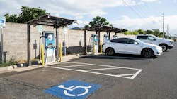
As defined in NEC 2023 Art. 100, EVSE includes the power block, pedestal, charging cables, wiring, and any accessories necessary to transfer energy between the premises’ wiring and the EV. This article will focus on plug-in charging stations (as opposed to pantograph charging or induction charging technology) because they are more broadly commercialized for personal vehicles. As such, future mention of EVSE in the article will specifically refer to plug-in charging stations and not consider overhead or wireless charging — or any other technology such as bidirectional charging.
EVSE is typically categorized into three levels: Level 1, Level 2, and Level 3. The levels are detailed as follows:
- Level 1 charger — These chargers typically use a 120V alternating current (AC) branch circuit, which can be provided via a standard three-prong household plug (i.e., National Electrical Manufacturers Association [NEMA] 5-15P or 5-20P) that is plugged into a standard receptacle. The power output of a Level 1 charger is typically around 1kW to 2kW. Because of the low power output, it takes a substantial amount of time for the car battery to be fully charged (more than 40 hours to charge an EV with a 60kWh battery from empty to full). Therefore, this charger is typically only used in residential homes — where long overnight charging makes more sense.
- Level 2 charger — These chargers typically use 208V to 240VAC power inputs and can output roughly 7kW to 19kW of power. With a higher power output, the Level 2 chargers provide improved charge times when compared with the Level 1 chargers (approximately 10 hours to fully charge an EV with a 60kWh battery from empty). These are the more commonly seen chargers in public charging locations, at workplaces, and at residential homes.
- Level 3 charger — These chargers are also known as direct current fast chargers (DCFC) and typically use a 3-phase 480V or 208VAC power input that is then converted to output 200V to 1,000V direct current (DC). Unlike Level 1 and Level 2 chargers, the power is delivered directly to the battery without having to be converted from AC to DC inside the EV. As such, this minimizes the time of the charging from hours to minutes and can output between 50kW and 350kW. These chargers are increasingly becoming more common in public places and are a common solution for electrifying bus or commercial truck/van fleets. However, DCFC is more expensive and has a high power demand compared to Level 1 and Level 2 chargers. In addition, not all existing structures have readily available 3-phase 480V or 208V power or electrical infrastructures to support higher-powered DCFCs. In other words, installation of DCFCs may require retrofits or power distribution upgrades.
Although Level 3 chargers are more expensive and require more power than a Level 1 and Level 2 charger, a charge management system and additional cables per charger could potentially make it a more affordable purchase, depending on vehicle and charging protocol duty cycle requirements. Careful consideration of the available options and operation could make Level 3 chargers or a combination of the three types more feasible.
The Society of Automotive Engineers (SAE) International is a professional organization that has developed standards for EV charging connectors. The most common connector for Level 1 and Level 2 charging is the SAE J1772 connector, which is compatible with most EVs. Tesla EVs typically use the North American Charging Standard (SAE J3400 connector); at present, an SAE J1772 adapter is included with every Tesla EV. The SAE J3400 connector can also be used for the DCFC. However, the combined charging standard (CCS) connector is commonly used for DCFC. The connectors are referred to as CCS because of their capability to support not only DCFC but also Level 1 and Level 2 chargers (because they use several of the pins from the SAE J1772 connector).
The case study’s new administrative facility has voltage available for all three types of chargers. Since this is an office and/or lab space, the employees are expected to be on site for 8 hours (a typical workday); as such, only a Level 2 charger and DCFC will be considered an applicable option.
Limiting factors
When determining the charger selection, consider any potential limiting factors. Budget is typically a prioritized consideration for any project installation. In this case, DCFC is more expensive than the Level 2 charger and may also require electrical equipment upgrades, which would make the Level 2 charger more cost appealing.
Another limitation to consider is the power demand from the chargers and the budget for the installation of EVSE suitable for the power demand. DCFC requires more power, and the electrical equipment upstream of the charger needs to be capable of handling the power demand. This may be more costly and require more space for higher-rated equipment.
Consideration of the employees using the EVSE is also vital. Does the EV need to be charged within minutes or hours? Are the employees required to travel long distances or often from the facility to a site or client? Is it reasonable to expect employees to move their vehicles to/from a charger midday?
With all these considerations (and many more not mentioned in this article), two Level 2 chargers rated 208V, single-phase, 32A input max, 6.6kW max with a SAE J1772 will be used for this case study. This would allow a small handful of employees to “top up” their charge to reduce range anxiety during their commute.
Applicable codes and guidelines
It is essential to provide an EVSE that meets the client’s needs while adhering to the federal, state, and local requirements and guidelines. This article will mainly consider the National Fire Protection Association (NFPA) 70, 2023 Edition, which is also known as the National Electrical Code (NEC). While the NEC provides minimum requirements to prevent overheating and fire, it is not meant to be used as a design book.
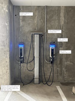
Two Level 2 chargers will be mounted on separate pedestals in front of their respective parking spaces. In other words, the EVSE will be considered fixed-in-place equipment. An example of Level 2 chargers in a parking garage is shown in Photo 1.
Typically, manufacturers will provide all the necessary EVSE, including the charger, output cable from the charger to the EV charging connector, the EV charging connector, and the pedestal and mounting accessories. When determining the output cable from the charger to the EV, Sec. 625.17(B) states that the cable shall be type EV, EVJ, EVE, EVJE, EVT, or EVJT flexible cable.
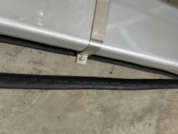
Photo 2 shows the output cable from the chargers in Photo 1. NEC Table 400.4 provides more details about the cable type, including cable size, insulation thickness/type, and usage. The overall cord length, per Sec. 625.17(C), cannot exceed 25 feet without a cable management system. As such, for this case study, a 25-foot cable will be specified; however, to keep the EVSE looking clean, a cable management system (e.g., cable retractor) will also be included.
Per Sec. 625.40, an outlet installed for EVSE that is rated over 120V, or greater than 16A, is required to be supplied by an individual branch circuit; however, if a branch circuit is used instead of an outlet, multiple EVSEs can be fed from one branch circuit if (1) there is an energy management system that limits the maximum load or (2) the adjustable current settings comply with the manufacturer’s instructions and are represented via a rating label that can endure the environment in which it is installed.
If the current settings are adjustable, they are required to be sealable and only accessible to qualified personnel, as per Sec. 750.30(C). Since there are only two EVSEs for this case study, both rated at 208V single-phase 32A max, an energy management system will not be provided, nor will protective devices with adjustable current settings be provided. The two Level 2 EVSEs will be on their respective branch circuits to ensure separate power connections for maintenance purposes (i.e., if one EVSE needs to go offline, the other EVSE can still be usable without shutting off the breaker to both).
The EVSE is considered a continuous load by the NEC. As such, all services and feeders must be sized per the EVSE ratings and must not be less than 125% of the maximum load of the equipment (Sec. 625.41). Sizing of the protective device for the EVSE and for the branch circuit is specified by Secs. 240.4, 310.16, and any other applicable NEC sections.
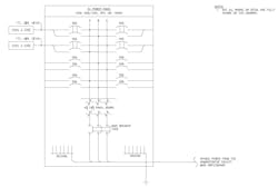
With a rating of 208V, single-phase, 32A input max, 6.6kW max, the conductor size must be 32A × 125% = 40A. Assuming a 75° temperature rating, a #8 American Wire Gauge (AWG) cable (NEC Table 310.16) and a #10 AWG equipment grounding conductor (NEC Table 250.122) are sufficient. If the conductors are THWN, a 1-inch conduit could be used (NEC Table C.13(A)). The Level 2 EVSEs will be fed from one dedicated EV panelboard located within the administrative facility. With only two EVSEs rated 32A max, a standard 100A panelboard with 42 poles is sufficient. The Figure above shows the panelboard layout.
About the Author

Lilly Vang
Lilly Vang is an electrical engineer at CDM Smith. She focuses on the design and analysis of low/medium voltage electrical power systems.


