The Path of Least Resistance
One of the most dangerous ideas circulating in the electrical industry is that electricity follows the path of least resistance. But if it did, not a single one of our electronic gadgets would work.
This concept is not taught in any engineering school. In fact, it contradicts what is taught. Yet, you can hear this stated, even among electricians and engineers, as if it’s true. Not only is it stated, but it’s followed in practice.
We see it most often in grounding applications. You can walk into many plants and find a motor that is tied to a ground rod. Individually, ask each person in electrical maintenance department why there’s a ground rod connected to the motor. Ask them if that was done to eliminate differences of potential, and the odds are most of them will say yes. Same thing will probably happen if you ask the plant electrical engineer.
But is this what that connection actually does? You can answer this question by drawing out the circuit and applying Kirchoff’s Law of Parallel Circuits. That’s the same law that first year electrical students apply to determine the value of one resistor that’s in parallel with another resistor.
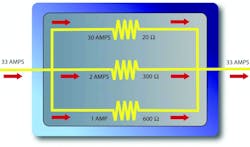
Let’s look at that first year problem, first. You have two 100 ohm resistors in parallel. What’s the total resistance? It’s 50 ohms. If you had only one 100 ohm resistor, the resistance would be 100 ohms. But add another, and it’s half the resistance. That’s because you added a parallel path and it’s flowing through not just one path but two. Using a water analogy, you double the total flow when you put a second four inch pipe in parallel with the first one.
If electricity actually took the path of least resistance, the answer would be 100 ohms. Since both paths are equal, electricity would arbitrarily go through either path. But that’s not what happens. It flows through both paths in inverse proportion to the resistances presented to it.

Grounding the motor does what, exactly? Well, that grounding connection is one of several parallel paths that electricity could take. The motor bearings are another. So is the operator who decides to put one foot on that ground rod and another on the motor, an act that puts his heart in a parallel current path with the motor.
Electricity tries to get back to its source. The impedance of the dirt between that ground rod and the supply transformer is much higher than the 100 ohms of the typical human body. If enough stray current is present, that operator could be electrocuted while standing on the ground rod.
By now, you may be forming a mental picture. Now put it on paper. Draw that motor and draw the circuits that exist in parallel with the motor grounding connection. Write in the ohmic values, and you can see that grounding connection is most certainly not eliminating differences of potential.
About the Author

Mark Lamendola
Mark is an expert in maintenance management, having racked up an impressive track record during his time working in the field. He also has extensive knowledge of, and practical expertise with, the National Electrical Code (NEC). Through his consulting business, he provides articles and training materials on electrical topics, specializing in making difficult subjects easy to understand and focusing on the practical aspects of electrical work.
Prior to starting his own business, Mark served as the Technical Editor on EC&M for six years, worked three years in nuclear maintenance, six years as a contract project engineer/project manager, three years as a systems engineer, and three years in plant maintenance management.
Mark earned an AAS degree from Rock Valley College, a BSEET from Columbia Pacific University, and an MBA from Lake Erie College. He’s also completed several related certifications over the years and even was formerly licensed as a Master Electrician. He is a Senior Member of the IEEE and past Chairman of the Kansas City Chapters of both the IEEE and the IEEE Computer Society. Mark also served as the program director for, a board member of, and webmaster of, the Midwest Chapter of the 7x24 Exchange. He has also held memberships with the following organizations: NETA, NFPA, International Association of Webmasters, and Institute of Certified Professional Managers.