Cut the Cord, Keep the Code: Wireless Control for Code-Compliant Emergency Egress
Key Takeaways
- Emergency lighting must provide sufficient illumination for safe egress during power outages, with performance validated through on-site testing and AHJ approval.
- Codes like NFPA 101 and the NEC set performance criteria, while UL standards ensure product reliability; both are essential for compliant emergency lighting systems.
- Design options include centralized, distributed, maintained, and non-maintained solutions, each suited to different building layouts and retrofit needs.
- Advanced controls, including UL 924-compliant devices, wireless systems, and dimming technologies, enable flexible, energy-efficient emergency lighting without compromising safety.
Emergency lighting has one job: keep people moving safely when normal power fails. Put simply, it’s the system that keeps a safe level of illumination — and power for lighting-related critical equipment — when normal power fails, so people can get out of the building safely. What makes it different is that it’s a life-safety system. So decisions can’t be driven only by cost or convenience.
In some applications, the right solution may be pricier than ambient lighting — though, as we’ll see, new technology can actually lower cost while improving emergency light quality. In addition, compliance is performance-based, not product-based. As such, a UL mark alone doesn’t guarantee it was used in a well-designed project or the right application; the system tested on-site must prove required performance, as designed recommendations per building codes, including the expected maintained illumination for a minimum time.
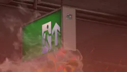
As for using lighting controls to provide the right emergency lighting at the appropriate time, the building codes themselves are largely technology-neutral, which is why controlled solutions are viable — as long as they meet the performance requirements. Although advances in lighting controls and energy management have made code compliance more complex, they’ve also unlocked better options — with higher-quality emergency lighting, easier testing and maintenance, and simpler design and installation efforts. Educational facilities (Photo 1) are a great place to implement a modern lighting control system.

When did it all start?
Did you know it all started with too many standards for sprinklers’ piping size and spacing back in 1895? Due to the multitude of options, some insurers and engineers united to recommend uniform sprinkler sizes and spaces. The group’s work resulted in NFPA 13, Standard for the Installation of Sprinkler Systems.
The NFPA was founded in 1896 to bring uniformity to fire protection. One year later, the first National Electrical Code (NEC) set common safety rules for wiring. Shortly thereafter, by 1911, the NFPA had taken over sponsorship of the NEC and has maintained it ever since. On the life-safety side, NFPA’s Committee on Safety to Life published the 1927 Building Exits Code after studying deadly fires; that lineage evolved into NFPA 101, Life Safety Code.
Today’s emergency lighting equipment and systems trace back to the 1927 Building Exits Code, which was founded on a simple principle: Occupants must not be left in the dark. A century later, that performance-based, technology-neutral foundation remains intact — focused on ensuring safe visibility and egress, regardless of whether activation comes by wire or radio.
What does the code ask for?
Think of it in three layers (Photo 2). First, the building codes (NEC Art. 700, etc.) govern power sources, transfer equipment & systems, separation/identification of emergency circuits, testing, and documentation. This basically means that across adoptions of NFPA 101 and the International Building Code (IBC), designers must provide, along the means of egress, an initial 1 fc average (≥0.1 fc minimum) at the floor, allowed to decay to 0.6/0.06 fc by 90 min., with uniformity ≤ 40:1. Stairs carry a 10 fc requirement in normal operation. These values are technology-neutral: The code doesn’t mandate how you get there — only that you do, and that the system behaves automatically on power loss. NEC Sec. 700.24 clarifies directly controlled emergency luminaires vs. bypass/force-on methods; Sec. 700.11 sets rules for Class-2 emergency circuit identification, separation, and protection.

Knowing that we have design guidance per safety codes, do you feel safer now? If you do, you shouldn’t. What about the products used? How do we know they were designed to support such requirements and in a sustainable way?
Here comes UL!
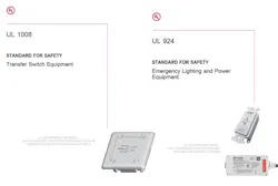
This is when product standards come in and govern what the equipment is listed to do (Photo 3).
UL 924, Emergency Exit Signs, covers emergency lighting and power equipment: exit signs, unit equipment, micro- and central inverters, and emergency lighting control devices (ELCD/ALCR) that force luminaires to the emergency state. It also covers directly controlled emergency luminaires (DCEL) that accept a dedicated emergency input.
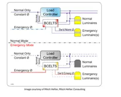
UL 1008, Transfer Switches, covers transfer switch equipment, including branch-circuit emergency lighting transfer switches (BCELTS).
Field rule: If you’re changing sources, that’s UL 1008. If you’re overriding control/forcing full output, that’s UL 924. We won’t address UL 1008 here because it’s not directly related to lighting equipment.
Do you feel safer knowing we have design guides and certified products? I hope so. But we're not done yet. The equipment and systems still need to be inspected and tested.
Authority Having Jurisdiction
This step involves the Authorities Having Jurisdiction (AHJ), defined by NFPA as the organization or person that enforces the code or approves an installation, reviewing listings, the sequence of operations, and the test plan, and then witnessing tests on site. The entire system needs to be evaluated as installed and eventually accepted by the AHJ.
The AHJ evaluates performance on site. If approved, they enable a Certificate of Occupancy (CO). Non-compliance can trigger corrections or a provisional CO with deadlines. After the building is opened to occupants, upkeep is mandatory: the 2026 NEC Sec. 700.4 adds Commissioning and Servicing—(B) Tested Periodically requires a testing schedule approved by the AHJ, and (D) Record Keeping requires written or digital records available to those who design, install, inspect, maintain, and operate the system. In parallel, 2024 NFPA 101 §7.9.3 requires periodic testing of emergency lighting equipment.
Who plays AHJ? For example, in New York City, it’s the Department of Buildings (DOB) with FDNY inspectors. In Canada, it’s typically the municipal building official (often alongside the provincial electrical authority).
How does this happen in reality, and what are the typical solutions? We can separate emergency lighting control solutions into four categories.
Centralized vs. distributed
Centralized vs. distributed emergency lighting boils down to where the backup power lives and how it reaches the luminaires (Photo 4). In a centralized approach, a generator or central lighting inverter (EPSS) feeds selected circuits so the normal luminaires ride through an outage. This is a great option for large corridors and open areas because it means fewer batteries to service, and it results in clean ceilings. However, it can mean heavier upfront infrastructure and careful circuiting.
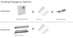
In a distributed approach, backup power sits at the edge — unit equipment (bug-eyes/combos), LED emergency drivers inside fixtures, or micro-inverters per fixture/zone. This configuration is ideal for retrofits and offers targeted wayfinding with minimal new conduit. However, it spreads batteries and maintenance across the floor.
Most modern designs blend both: centralized coverage for big spaces, distributed devices where wiring is hard — all coordinated by code-compliant controls (UL 924/UL 1008) to ensure maintained or normally-off paths meet 90-minute, illumination, and fail-safe requirements.
Maintained vs. non-maintained (why it matters with controls)
- Maintained (normally on): part of everyday lighting; must force to emergency when power is lost — even if the space was dimmed. Use ELCD/ALCR or DCEL.
- Non-maintained (normally off): only energizes in an outage, typically via inverter/generator or local battery.
Show me how
Now it’s time to review traditional and newer approaches for emergency lighting. It’s easier to illustrate these concepts with fewer words and more visuals. See graphics below for the following scenarios:
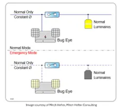
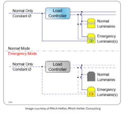
Approach No. 1: Unit equipment (bug-eyes/combos) and LED emergency drivers provide local battery back-up where circuits are hard to reach, or you want targeted wayfinding light (Fig. 1).
Approach No. 2: LED emergency drivers provide local battery back-up where circuits are hard to reach, or you want targeted wayfinding light (Fig. 2).
Approach No. 3: Central inverters/generator (EPSS) keep normal luminaires on during outages — great for large open areas and corridors, and to reduce battery proliferation (Fig. 3).
Approach No. 4: Micro-inverters (fixture/zone) deliver full-output ride-through with minimal rewiring (Fig. 4).
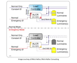
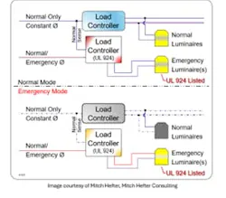
Approach No. 5: For controlled spaces, add UL 924 ELCD/ALCR (bypass/force-on) or specify DCEL luminaires so dimmed scenes cannot suppress the emergency state (Fig. 5).
The control dilemma
Can lighting controls used to enhance lighting quality and energy savings also play a role in emergency lighting? After all, this is a lighting control article, right?
In a lot of projects, lighting controls are required by energy codes to turn lights off or dim them during normal operation. Yet emergency lighting must provide a reliable path of egress that those same controls cannot turn off. How can two seemingly opposite requirements coexist — sometimes even within the same luminaire?
In May 2020 (effective May 2022), UL added Clause 29A to UL 924 and tied it to the ELCD test sequence in 47.2(c), which states that if an Emergency Lighting Control Device (ELCD) provides control functions — on/off/dim — it must continuously monitor the “normal-power present” signal for its controlled branch circuit. That monitoring can be wired or wireless, but it must remain functionally independent of the emergency power feeding through the device. In other words, even while passing emergency current, the ELCD must still watch normal-power status and respond automatically and fail-safe.
This is the technical bridge that finally lets general lighting controls participate in emergency-lighting control. When implemented with UL-listed ELCDs or directly controlled emergency luminaires (DCELs), the same control infrastructure that dims, senses, and reports during everyday use can — upon loss of normal power — automatically shift into emergency mode, delivering required illumination while preserving code compliance. Why? Because the key factor is a system with a fail-safe behavior: The control system may add intelligence, but the UL-924 device guarantees that light comes on even if the regular power signal monitored by the control system disappears, or if the system overall disappears.
There is no pre-set dimming anymore, nor is there an end-user changing the light levels from a wall station.
Aren’t we trying to do the opposite per the latest energy building codes?
Yes, both building and energy codes are designed to coexist: Life safety wins in an emergency, and energy efficiency governs in normal operation. Most energy codes (Title 24/ASHRAE/IES 90.1, and IECC) exclude emergency lighting that is normally off from lighting power and control requirements, so dedicated emergency luminaires aren’t penalized for being "ready-but-off." For maintained luminaires (used every day), you still meet energy rules (dimming, occupancy, daylighting) until normal power is lost; then, a UL 924 override or directly controlled emergency input takes priority and drives the required emergency level for 90 minutes.
Here’s a summary of U.S. energy-code exceptions.
- ASHRAE/IES 90.1 excludes normally off emergency lighting from its lighting power and control scope.
- IECC 2021 likewise exempts 24-hour emergency/security lighting and emergency egress lighting that is normally off.
- California’s Title 24 allows up to 0.1 W/ft² of designated means-of-egress lighting to remain continuously on without the usual area/automatic shutoff controls.
Show me the money
Using a 0-10V dimmable luminaire with central inverters with 0-10v dimming capabilities lets you keep everyday lighting quality and still meet emergency egress requirements — with better, more uniform light during outages (Fig. 6). Under normal power, the inverter simply passes through the room’s 0-10V control, so your maintained luminaires behave like any other dimmable load. If normal power fails, the inverter generates AC from its battery and takes control of the 0-10V line, driving the luminaires to a predetermined emergency level that fits the inverter’s rating (e.g., a 40VA luminaire in normal mode can be auto-dimmed to ~10VA in emergency). The result is code-minimum egress illumination with less glare, better contrast, and more luminaires on (at a safe reduced level), while acknowledging real-world inefficiencies may modestly reduce the total achievable load.
DALI
As we know, DALI control systems communicate on a low-voltage control bus to LED drivers and other control gear. During an emergency, the power continuity still comes from your EPSS (generator/central inverter) or local batteries. In normal operation, DALI runs scenes, occupancy/daylight, and keeps DALI emergency devices (IEC 62386-202) on a schedule for self-test and status reporting. When normal power is lost, two things happen: (1) the emergency power source keeps the designated circuits/luminaires energized, and (2) the emergency input/logic takes over — either a UL 924 interface forces maintained luminaires to the required output (bypassing dimming), or DALI Emergency control gear inside the luminaire automatically switches to its emergency state at a defined level and logs the event. Because the emergency behavior lives in the listed device, luminaires go to (and hold) the code-required output without relying on the central controller, while DALI still gives you grouping, test automation, and fault reporting to prove compliance.
Keep in mind that a DALI system, when disconnected, doesn’t fail to high as 0-10V. In addition, the emergency lighting scenes need to be programmed. Self-contained emergency is included as part of DALI-2 certification. It typically includes support for function and duration tests, next to drivers going into emergency mode upon mains power failure.
DALI Alliance released to its members a new Part 254, which extends the emergency specifications with information on batteries. Although not released yet or part of the certification program, there is work being done by the DALI Alliance around centrally supplied emergency lighting.
DMX512
Similar behavior can be achieved with a DMX512 system. This is a good solution for theatrical lighting-related applications, such as theater or sports-related environments. DMX512 is a unidirectional show-control protocol that streams levels to luminaires; it doesn’t provide power continuity — that still comes from your EPSS (generator/central inverter) or local batteries.
For egress lighting, you must make DMX fail-safe: Insert a UL 924 emergency interface (or ELCD/ALCR) that, on loss of normal power or on an emergency contact, overrides DMX and drives designated channels/luminaires to the required emergency level (typically full). Don’t rely on a console or “hold last look/blackout” loss-of-signal behavior; instead, wire an emergency input from the EPSS/fire alarm/inverter to the UL 924 device or architectural DMX controller’s emergency input so the scene changes automatically. Document which DMX universes/channels are egress, show that dimming is bypassed in emergency mode, and keep the emergency circuits/luminaires energized by the listed source. If you use RDM/sACN for monitoring, treat it as supervision only — the listed UL 924 override is what satisfies the life-safety requirement.
How about wireless solutions?
The recent twist is that we can often deliver those outcomes with far fewer new wires by pairing listed emergency devices with a wireless control/supervision layer. The result is faster retrofits, cleaner ceilings, and better testing/records without compromising life safety.
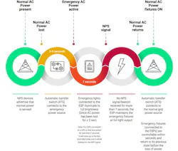
Figure 7 illustrates the full sequence of operation when normal AC power is interrupted. Under normal conditions, NPS devices broadcast that electric utility power is present, and all luminaires operate in their normal, controlled mode. When normal power is lost, the automatic transfer switch (ATS) shifts to the emergency source within 3 to 5 seconds. After 2 seconds of power loss, emergency luminaires on the ESP drive to full output. If no NPS signal is received for more than 7 seconds, the ESP keeps those emergency lumianires at full brightness until normal AC power is restored. Once electric utility power returns, the ATS reconnects to the grid, and the emergency luminaires quickly transition back to their previous, non-emergency lighting state.
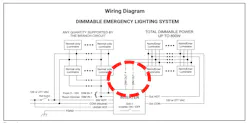
This solution includes selected lumianires to be wired to the emergency power system and deliver emergency lighting, and other selected luminaires providing the normal power signal (NPS), sometimes referred to the heartbeat or beacon, to communicate that the regular power is present on site (Fig. 8). Wireless is not your life-safety source; the emergency power source and any power transfer devices remain your hard-wired and listed source.
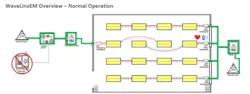
The wireless solution, mostly a mesh network solution, needs to be designed with layers like critical plumbing: stagger broadcasts, avoid network-wide floods, and ensure each emergency device has a local fail-safe path that does not depend on receiving a packet at the worst moment. In other words, optimize to prioritize emergency beacon signals, versus traditional control commands such as manual switch dimming, daylighting override, or a scheduled dimming action for a specific zone. If the beacon signal isn’t prioritized and is not received by an ambient luminaire acting as an emergency luminaire, it will default to high or its emergency lighting pre-programmed level. Fail-safe, but unnecessary overrides on-site are to be avoided (Fig. 9).
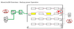
The mesh continually heartbeats the NPS beacon signal as defined by UL924 and seen earlier in the text; if heartbeats stop, emergency devices go to emergency light level output, something their full output or other planned leveler per minimum level requirements. Outside emergency lighting mode, an override command can be sent so luminaires go to the required emergency state on loss of normal power or control for testing, or site inspections.
The same system backbone can provide supervision and testing with an instant access to the status of your system and constantly monitor is status, and not only when scheduled for testing or inspection. It can automate and performs all required testing monthly 30-sec and annual 90-min. tests, store digital logs and or email reports — a must for AHJ audits, with no searching for reports during an inspection. There are no ladders, no pushing buttons, and no documentation; reports can be easily exported to prove the system status is 100%.
Conclusion
The bottom line is emergency egress lighting isn’t about gadgets — it’s about outcomes: the right light, for long enough, every time. The good news is that modern, technology-neutral codes let you pair proven life-safety hardware (UL 924/UL 1008) with smarter control layers — wireless meshes, DALI Emergency, 0–10V with inverter auto-dim, and even DMX with UL-924 overrides — to deliver better visibility, simpler installs, and automated testing/records.
If this article sparked ideas, take the next step by piloting a small zone that blends your everyday controls with a listed emergency method, document the fail-safe sequence, and review it with your AHJ. Then scale what works — add self-test reporting, digital logs, and wireless supervision — to reduce OPEX while raising safety and light quality. Cut the cord where it helps, keep the code where it counts, and keep learning — because the fastest path to safer buildings is staying current on the tools that make compliance easier and outcomes better.
About the Author

Martin Mercier, P.Eng.
Mercier, P.Eng., is strategic marketing manager for IoT and connected systems for Cooper Lighting Solutions, a division of Signify (formerly known as Philips Lighting), based in Peachtree City, Ga. Previously, he was a senior product manager for advanced lighting technology systems for the Americas for eight years with Signify. Since his early days in R&D, he contributed to develop and launch the patented first Philips Lighting LED light engine plate-form deployed in multiple brands and manufacturing sites across the Americas. Shortly after, he helped to bring early cloud-based technology lighting systems for public and private customers in the Americas to market. His insights and ideas helped to strengthen the overall effort in pioneering new technologies for Signify and the lighting industry in general bringing problem-solving solutions for smart city and smart building customers. Detail-oriented and technically gifted, Martin studied electrical engineering at the renowned École de technology supérieure – the largest engineering school in Quebec. He can be reached at [email protected].