Leveraging Low-Voltage DC Power
The forces for change in the building environment are constantly pressuring electrical systems to do more. The most recent example is the expanded use of solid-state LED lighting technology and the extensive use of electronic drivers and controls. The increasing use of so-called “smart” devices, which can seamlessly be used in plug and play form, will further the march toward the Internet of Things. In addition, the evolution to enterprise-level microgrids that can harness the potential of massively distributed on-site power generation, the increasing use of variable-speed drives and electronically commutated direct current (DC) motors, and the arrival of plug-in electric vehicles all herald the inevitable use of low-voltage DC power in buildings.
Despite these advancements, there are some issues that must be addressed along the way before we realize all the benefits of this new technology. One is how — and in what form — we distribute the power for this new wave of electro-activity in buildings. Many new power sources and uses of electricity operate on DC power at lower voltages. Increasing AC to DC power conversions and conditioning are lowering power generation and consumption efficiency, and system complexity is reducing equipment and system reliability. This is paving the way for change in the way we deal with power at the building level. New power distribution methods are providing solutions to the problem of the growing mismatches in our power systems. The subject of this article — new Art. 393 of the 2014 NEC — is helping to make it possible for these new solutions to find their way to safe and effective commercialization.

Scope of Art. 393
Article 393 [Low-Voltage Suspended Ceiling Power Distribution Systems] covers the installation of low-voltage suspended ceiling power distribution systems and associated equipment. These systems comply with UL2577: Standard for Safety for Suspended Ceiling Grid Low-Voltage Systems and Equipment. The UL Category Code is IFFC: Suspended Ceiling Grids and Suspended Ceiling Grid Low-Voltage Accessories (Fig. 1).
Article 393 restricts such systems to 30VAC or 60VDC maximum and 100VA maximum per circuit. Therefore, the maximum current is 100 divided by the voltage used. The EMerge Alliance Occupied Space Standard for ceilings compliant to this Article is based on a 24VDC distribution, but it should be noted that common utilization equipment may use other voltage by using buck or boost converters downstream of the distribution (e.g., converted to 5VDC, 9VDC, 12VDC, 19.5VDC, 48VDC, etc.).
Article 393 applies to indoor, dry, exposed locations as is further defined in the NEC. It specifically applies to residential, commercial, and industrial applications. It covers special locations including “Other Space Used for Environmental Air” and can apply to a fire-rated floor-ceiling or roof-ceiling assembly when listed as part of the assembly. The non-energized suspended ceiling grid is considered structural; therefore, it is not addressed by the NEC. However, other building codes may apply to it, including seismic requirements.
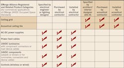
Components used in compliant systems must be listed by a Nationally Recognized Test Laboratory (NRTL) to UL2577 requirements and appropriately labeled as such. This includes the portion of the ceiling grid that includes conductors. Even low-voltage components are listed. The listing may be as a system or individual components (fittings).
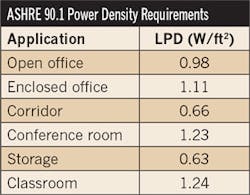
Although Class 2 power limits may seem restrictive from a wattage and wire loss standpoint, when practically applied to code-driven power density limits (Table 1), they end up being more than adequate.
Listed components of Art. 393
A full system covered by Art. 393 includes:
1. Low-voltage Class 2 power supplies (sources).
2. Low-voltage wiring, cables, and grid busses (interconnect).
3. Low-voltage common utilization equipment (loads).
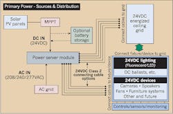
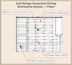
Starting with power sources, the key component is the power server module. A power server module (PSM) is typically configured to have between one and 32 channels of low-voltage Class 2 power output. The power source for the power supply can be either AC or DC, depending on the upstream power system configuration. In systems that are converting line current AC, the input AC is typically between 240VAC and 277VAC. In systems that use direct feeds from on-site alternate energy sources, such as solar, wind, fuel cell, and other native DC generation, the input voltages are typically in the 350VDC to 400VDC range. DC inputs eliminate the DC to AC conversion losses typical in AC distribution systems. Many PSMs have integrated control and other power management features, including branch switching and monitoring/dimming. These features can be extremely useful when “always-on” power is not required on some channels. Communication to the PSM can be wired or wireless and may include such protocols as ZigBee, IPv6, 0V-10V, Modbus, etc. The interconnect (wiring) components include:
1. Grid bus
2. Power feed cables
3. Power load cables
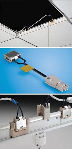
The ceiling grid mounted bus component provides flexible plug locations for the power load cables, but has fixed position connections for the power feed cables to control total wire lengths that limit low-voltage wire loss. A variety of actual interconnect components available from suppliers are depicted in the group of Photos to the right.
Specially keyed connectors on the power feed cables used between the PSM and the grid bus prevent the bus from being over-powered. This is an important feature of the system and should not be overridden or tampered with, or the system may end up in violation of the NEC.
An important option in the wiring scheme is the ability to power devices directly from the PSM. When doing so, it is important to remember to use Code-compliant wiring conventions for standard low-voltage Class 2 power and realize that these connections will be less convenient if future modifications are needed. However, they can be especially useful when the load devices are not located in or near the ceiling grid or when other reasons prevent the use of a bussed ceiling grid.
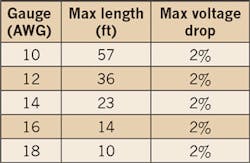
Wire loss and/or voltage drops in the system are limited by the proper use of wire gauge and length. Although not part of the NEC, these variables are specified in the EMerge Alliance standards that use this type of system. Typical gauge and length restrictions used to maintain losses similar to those found in functionally competitive AC system are shown in Table 2.
Typical appliances used in or near powered ceiling grids may include the following:
• Lighting (incandescent – HID, fluorescent, LED, and daylighting shades and louvers).
• Controls (sensors, master controllers, and wireless links).
• AV/IT (powered speakers, remote amplifiers, and displays/monitors).
• HVAC (controls, VAV boxes, fans, sensors, louvers, and automatic valves).
• Security equipment (cameras, controllers, recorders, motion detectors, audio detectors, and automatic doors & locks).
The practical wattage limit of any single channel power fed device is 95W. Luminaires that use less than 45W are typical.
Specification and design of compliant systems
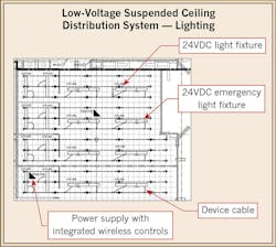
Most people are familiar with the drawings and documentation for branch and appliance wiring for line voltage systems, but these change when a low-voltage ceiling grid distribution system is specified (Figures 2a and 2b). In essence, the power is distributed along busses that cover the room space. Power connections between the PSMs and the busses are fixed and provide a uniform availability of power throughout the space. This allows significant freedom in locating and re-locating devices within the space without the need for re-wiring. It also allows a higher degree of control articulation because the bus channels can be thought of as mini-branches that can be separately controlled and monitored. Connection “whips” on devices typically allow a choice of connecting to two to four different channels within easy reach so channel overload (which is automatically detected) can be avoided.
Unused busses can be prewired or added later to minimize initial material cost, if desired, although any increased initial equipment cost is quickly recovered in common reconfiguration cost savings. It’s a “pay a little more now to save a lot later” scenario. However, either way, typical cost for equivalent functionality can be very competitive, especially when advanced functionality (direct renewable energy sources, highly controlled and articulated power, enhanced monitoring, etc.) is required.
One other important requirement of system design is the correct specification of luminaire configuration. Specific ballast and/or LED driver input voltages must be specified correctly for the new power conditions.
When it comes to who is generally responsible for the layout, design, and documentation of the systems, the first important distinction is in the division between the ceiling structure and the electrical system. The suspended ceiling grid and tiles are still specified in CSI Div. 9 by the architect and purchased/installed by an acoustical or drywall contractor. The electrical components are specified in CSI Div. 16 or 26 by the electrical engineer and purchased/installed by an electrical contractor (Table 3).
With regard to the ceiling grid embedded bus, the electrical engineer simply needs to include a marked up version of the reflected ceiling plan that indicates which sections of the grid mains need to contain conductive bus. The grid embedded bus is not and cannot be connected electrically by the acoustical contractor and remains inactive or non-electrical unless and/or until activated through connections by the electrical contractor. This assures a traditional division of trades regardless of the configuration of electrical and structural components.
Typical bill of materials
The system is essentially comprised of two different categories of material and labor. First, let’s look at a typical bill of materials (BOM) for the acoustical/drywall contractor and the electrical contractor in a traditional system versus a low-voltage suspended ceiling distribution system (Table 4).
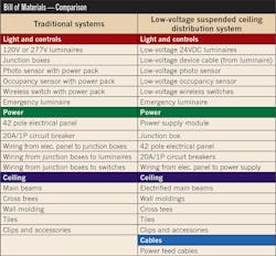
In both cases, the lighting, power, controls, and wiring are contained in the electrical BOM and the ceiling components are in the acoustical ceiling BOM. The two notable differences will be that the electrical BOM will now include system cabling, and the acoustical ceiling BOM will include embedded bus main beams. Otherwise, the BOMs are very similar to existing system configurations.
System installation
Regarding installation, both traditional AC and new Art. 393 systems follow the same construction sequence. While there are a few differences in what each step involves, the sequence is almost identical (Table 5).

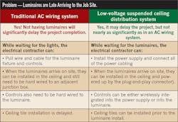
However, the new Art. 393 system does allow a few practical variations to mitigate common job hold-up issues, including delayed arrival of luminaires or other ceiling-mounted devices. Typically, ceiling tiles are not installed until all electrical devices are mounted and connected. But, since the new system is plug-and-play friendly, the majority (if not all) of the ceiling tiles can be installed before the luminaires with little risk to ceiling damage (Table 6).
Conclusion
Article 393 of the 2014 NEC now explicitly covers the installation and use of new low-voltage suspended ceiling power distribution systems. While previous versions of the Code also “allowed” for these systems, the new Code makes the requirements clear and avoids any confusion, misinterpretation, or misapplication. These systems are specifically being designed to take advantage of the desire and/or need to employ renewable energy sources at building sites, primarily to help achieve net zero energy goals and provide better system resiliency.
With relatively minor changes in the design, specification, and installation of such occupied space power systems, the use of low-voltage suspended ceiling power distribution systems can significantly contribute to making buildings more effective and versatile. By incorporating these lower level systems in a tiered network of local building microgrids (starting at the room level and proceeding all the way up to the common point of connection with the utility), they can lower energy consumption to provide better economic and environment impact for building owners and improve their sustainability and resiliency under a greater number of operational modes, including those involving power demand response or interruption.
Patterson is the president of the EMerge Alliance, a 501c non-profit corporation based in San Ramon, Calif., established to create application standards for DC power distribution systems use in buildings. He can be reached at [email protected].