Maintenance and Testing of Emergency Power Supply Systems
Over the years, the need for increased reliability of electrical systems is no secret to those in the electrical industry. Data centers, hospitals, emergency call centers, government buildings, and financial institutions are just a few of the types of facilities that demand reliable sources of backup power.
Couple an aging utility grid with a need for reliable power sources, and the standby generator immediately comes to mind. But what makes a backup power source so reliable? Just because it is a diesel or natural gas-powered power source, is it assured that — in the event of a loss of primary power — this alternate source will come online, supplying critical loads in the designated time, for the length of time needed, and at the proper quality of power? The answer is “no” — not unless there is reason to believe this emergency system has been properly maintained and put through an adequate testing program to provide reasonable confidence it will perform its needed function. Enter NFPA 110, Standard for Emergency and Standby Power Systems.
Emergency and standby power systems
NFPA 110 is the performance standard often specified by the Authority Having Jurisdiction (AHJ) to provide facility owners a consensus-approved standard by which their backup power system is classified, maintained, and tested.
NFPA 110 was first formally published in 1985. The standard includes the requirements for all components of the emergency power supply system (EPSS), which is much more than just a backup generator. It also includes the conductors, disconnecting means, overcurrent protection, transfer switches, control and supervisory circuits — in short, any components necessary to ensure this source of electrical energy will deliver a safe and reliable source of power is encompassed by the EPSS and are included in the maintenance and testing requirements of the EPSS (see Figure on page 18). The emergency system ends at the load terminals of the transfer switch. From these load terminals, the remaining components of the distribution systems are covered by other applicable codes.
The National Electrical Code (NEC) recognizes three separate types of standby power systems under Chapter 7, Special Conditions. Article 700 addresses “Emergency Systems.” Article 701 addresses “Legally Required Standby Systems.” Article 702 covers “Optional Standby Systems.” Since optional standby systems are just what they say, “optional,” they are not covered by NFPA 110. It classifies emergency systems based on three factors. First, systems are classified by their importance to life and health: “Level 1” or “Level 2.” Then, emergency systems are specified by “Class,” which is based on the amount of time the system must be capable of operating at full load without refueling. Finally, systems are specified by “Type”: the maximum amount of time the load terminals of the transfer switch may be without power. Maintenance and operational testing are used to verify the system will meet its classification requirements and ensure a reliable source of standby power to designated loads.
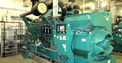
NFPA 110 uses the term Emergency Power Supply (EPS) in reference to a source of electrical energy that must be of “required capacity and quality for an emergency power supply system.” The EPS must be rotating equipment and driven by one of three types of engines: Otto cycle (spark ignition), diesel cycle, or gas turbine. For reasons of reliability, a diesel engine prime mover coupled to a 3-phase generator and mounted together as one unit (generator set) is the most common type of emergency power supply in use. A large part of maintenance and operational testing revolves around the diesel-driven generator set (Photo 1).
Required maintenance and testing
Preventive maintenance and testing, which must be performed by qualified persons, is conducted to help ensure system reliability. Manufacturer’s maintenance recommendations should always be used, yet these may differ from NFPA 110 minimum requirements. It is important to recognize and understand the differences and then blend information together (as needed) to meet the minimum specified by NFPA 110 or other AHJ requirements. NFPA 70B, Recommended Practice for Electrical Equipment Maintenance, provides information on testing and test methods. Two additional documents from the International Electrical Testing Association (NETA) provide information for maintenance tests to be conducted along with minimum test specifications: ANSI/NETA ATS, Standard for Acceptance Testing Specifications for Electrical Power Distribution Equipment and Systems, addresses initial acceptance testing, and ANSI/NETA MTS, Standard for Maintenance Testing Specifications for Electrical Power Distribution Equipment and Systems, addresses maintenance testing.
NFPA 110 requires acceptance testing of the EPSS upon completion of installation and that a maintenance program then be instituted. To develop and implement a maintenance program, consult the equipment manufacturer documentation, NFPA 70B, NFPA 110 and the above-mentioned ANSI/NETA standards. Be aware many other standards may also apply. These may include: NFPA 30, Flammable and Combustible Liquids Code and NFPA 70, National Electrical Code for installation information; NFPA 111, Standard on Stored Electrical Energy Emergency and Standby Power Systems for flywheel and battery type uninterruptible power supply (UPS) systems. The distribution systems connecting to the load terminals of the transfer switch are covered by separate documents such as NFPA 99, Health Care Facilities Code or NFPA 101, Life Safety Code.
Maintenance and operational testing
The following discussion references the highlights for maintenance and testing found in NFPA 110. Always consult the above references and others (as needed) along with working with the AHJ to establish the emergency power system maintenance and testing program.
Consideration must always be given to providing reliable power to emergency loads — especially before maintenance begins! If the generator set is out of service for maintenance, how will emergency power system requirements be met? Some maintenance items may require lockout of other components of the emergency power system, rendering that portion of the emergency system inoperable — if not the entire system. For example, maintenance on the automatic transfer switch (ATS) may require operation in a “bypass” mode. This would bypass power around the automatic components of the system, allowing them to be serviced while normal power is still supplied to emergency loads. Maintenance and operations personnel must be aware automatic operations of the transfer switch will not function in the event of a loss of normal power, thereby compromising the integrity of the emergency system.
Consideration must be given to providing other temporary sources of power during emergency system maintenance. Some emergency systems may already be designed with alternate sources of power for use when the emergency system is not available. Perhaps a system has two or more generators that can be operated in parallel to supply loads. However, one of the generators may be taken down for maintenance while the remaining generator(s) can be used to meet system needs. In some cases, a mobile generator may need to be rolled onto the site to provide temporary power for scheduled outages.
As always, for industrial equipment, manufacturer’s instructions should be relied upon for maintenance instructions and schedules. However, additional items will most likely apply for emergency systems based on NFPA 110 or other codes used by the AHJ. For emergency systems, the manufacturer is required to supply two sets of instruction manuals as a minimum. The manuals must provide the following information:
• Detailed explanations of system operation.
• Routine maintenance instructions.
• Detailed repair instructions for the generator set and other EPSS major components.
• Illustrated parts list with part numbers.
• Schematic drawings of the electrical system, including safety interlocks, control panels, annunciators and instrumentation.
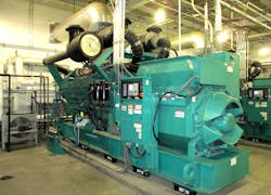
For Level 1 systems (Photo 2), one set of instruction manuals must be kept near the equipment in a secure location, such as a designated locker or cabinet. The other set is secured in a separate location. Any special tools required or necessary testing devices must be available. When possible, it is best to keep these tools and devices in marked cabinets. High mortality items and regularly consumed items, such as air and oil filters, must be kept on hand in a secure location. Other recommended spare parts should be available as well.
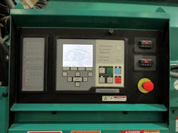
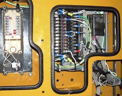
Engine starting batteries are one of the most common failure points of an EPSS. Checking liquid levels, keeping terminals clean and corrosion free, and regular maintenance of the battery charging system are key items for battery reliability. Electrolyte levels should be checked weekly for Level 1 systems and at least monthly for Level 2 systems. Terminals should be verified clean and tight quarterly, and an equalizing charge is recommended monthly. NFPA 110 has no requirement as to when engine-starting batteries must be replaced. Discharge testing can be used to test the capacity of these batteries; however, many facilities simply maintain and then replace these components on an annual basis — or at most every two years. In addition to manufacturer’s instruction, the ANSI/NETA MTS, Standard for Maintenance Testing Specifications, is always an excellent resource for developing maintenance procedures for batteries and other electrical components. Even verifying the tightness of control and other wiring terminations is addressed (Photo 3).
Fuel issues are another major cause of engine failure. Diesel fuel must be tested annually. Failure to maintain a diesel engine fuel system will assuredly degrade fuel quality. Water and contaminants are the major killers when it comes to diesel fuel. Water can damage fuel injectors, resulting in their complete failure. Water/fuel separators are used to help separate water and fuel, and must be maintained per the engine manufacturer’s instructions. Fuel filters can slowly become plugged with contaminants. Microorganisms can grow in diesel fuel and will not only contaminate the fuel, but also consume rubber seals. A common misconception is that adding new fuel to a storage tank will “refresh” old, stale fuel. In fact, adding new fuel will typically increase oxidation, further degrading the fuel. Proper testing, system maintenance, and fuel inventory management to keep fuel storage tanks full all play a big role in helping to ensure fuel quality.
The importance of lubricating oil goes without saying. Low lube oil pressure is required to shutdown both Level 1 and Level 2 systems. The obvious fear becomes engine damage. Lube oil levels should be checked weekly on Level 1 systems and monthly on Level 2 systems. Lube oil filters should be replaced every 50 operating hours, annually, or whenever needed. The lube oil heater is important for emergency operations as engines must start quickly and accept load. Emergency systems may require transfer switch load terminals to have virtually uninterruptible power, (as supplied from a station battery), or be supplied within 10 seconds. Most diesel-driven generator sets will be on the line and ready to supply full horsepower in 10 seconds or less. Lube oil not maintained at the manufacturer’s recommended temperature would prevent proper operation. Lube oil heaters should be checked at least weekly on Level 1 systems and monthly on Level 2.
Restrictions to intake air will only limit horsepower output. Air intake filters should be replaced as needed and changed per manufacturer’s instructions. Most generator sets have a service indicator attached to the air inlet to indicate when filters are beginning to show signs of restricted flow. Exhaust systems should also be visually inspected weekly for Level 1 systems and monthly for Level 2 systems. Condensate drains in the exhaust system should be drained and checked for proper operation at the same time.
If any component of the EPSS is repaired or replaced, which would affect the operation of the system, an operational test must be initiated at the ATS. Such a test would simulate the loss of primary power allowing maintenance personnel to verify that the repaired components function properly to transfer power to the standby source. The system must run on alternate power for at least 30 minutes during this test.
Diesel generator sets must be exercised at least once monthly for a minimum of 30 minutes. While this will help to ensure the unit will start and operate, it does not verify it will accept the necessary load. Additionally, not following manufacturer’s instructions or NFPA 110 requirements for engine loading will result in wet stacking. This occurs when a diesel engine runs lightly loaded. Carbon and unburned fuel will accumulate in the exhaust system, sending black smoke out the exhaust. Long-term results can include exhaust system corrosion and resulting engine damage, including fouling of fuel injectors and engine components. Thus, the 30-minute monthly test requirement must be conducted under a 30% kW load based on the standby kW rating on the nameplate, or by monitoring the exhaust gas temperatures as recommended by the manufacturer.
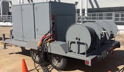
To create the needed load, load banks are typically employed (Photo 4). These large (depending on kW needs), air-cooled resistor banks are permanently or temporarily installed to provide kW load for testing purposes. Since resistive load banks operate at a power factor of 1.0, load banks may have inductors (coils) installed to more closely simulate the power factor that will be encountered by the generator control system.
Transfer switches must be cleaned, inspected, and the tightness of terminals verified. Main contacts should be inspected and cleaned annually. Voltage sensing relays used to detect a loss of voltage and when the alternate source is ready to supply power should be tested annually to ensure they operate at the proper values. Other control functions to be tested include timing relays or programs to automatically transfer power in specified periods of time. Transfer switches are to be operated monthly and may be done in conjunction with the monthly generator set exercise requirement. The transfer switch is tested by simulating a loss of normal power through controls at the transfer switch. Normal power will continue to supply loads through the bypass switch during testing operations.
Much more detailed maintenance and testing requirements are found through manufacturer information and NFPA 110. A comprehensive maintenance and testing program must be documented, scheduled, and implemented to meet NFPA 110, manufacturers, and AHJ requirements. While this article provides an overview to help ensure reliability, you must research and make sure your program meets all required specifications. After all, you’ve got to keep the lights on.
Barnett is a certified electrical safety compliance professional (CESCP). He can be reached at [email protected].
