Best Practices for Electric Motor Bearing Relubrication
Bearing failures are the most common cause of electric motor and generator failure. Maintenance professionals can optimize the life of these machines by following industry best practices for bearing relubrication frequency and quantity. Some considerations include:
- Is the lubricant grease or oil?
- Is it a ball, roller, or sleeve bearing?
- If it is a ball bearing, is the enclosure open, shielded, or sealed?
This article addresses grease relubrication frequency and quantity for ball and roller (rolling element) bearings separately from oil relubrication, viscosity and level (quantity) for ball, roller and sleeve bearings. It does not cover grease lubrication of sleeve bearings (rarely used) or sealed rolling element bearings, which do not require relubrication. A note of caution: Do not mix different lubricants because additives in them may not be compatible and could result in premature bearing failure.
Grease relubrication frequency and quantity for ball and roller (rolling element) bearings
Relubrication intervals
The frequency of relubrication is application and product specific, depending on parameters such as:
- Operating temperature
- Motor shaft speed
- Bearing size
- Bearing load
- Hours of operation
- Environmental conditions/contaminants
- Vibration levels
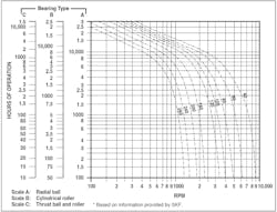
Figure 1 provides a simple chart for determining appropriate grease relubrication intervals for motors operating under normal conditions. To use it:
- Find the motor rpm on the horizontal axis.
- Draw a vertical line from the motor rpm to the curve for the bearing inside diameter (in millimeters) or the next smaller diameter.*
- From there, draw a horizontal line to intersect the hours of operation (relubrication interval) for bearing type A, B, or C.
- For motors operating in other conditions (e.g., vertical mounting, belt load, or hostile environments), reduce the relubrication interval from Fig. 1 by 50%.
* Note: The bearing inside diameter (D) in millimeters is five times the last two digits of the bearing number (e.g., for a 6211 bearing, D = 5 × 11 = 55 mm).
Example. Determine the relubrication frequency for a 6314 bearing operating at 1,750 rpm under normal conditions.
The inside diameter for a 6314 radial ball bearing is 5 x 14 = 70 mm. Since Fig. 1 has no 70 mm curve, draw a vertical line from 1,750 rpm to intersect the 60 mm curve (the next smaller diameter). Drawing a horizontal line from there to the column for radial ball bearings (Type A) indicates that the motor should be relubricated after about 11,000 hr of operation.
If the motor operates in a hostile environment, the relubrication interval would be reduced by 50% (0.5 × 11,000 = 5,500 hours). The relubrication interval for a cylindrical roller bearing (Type B) with the same bore size, such as an NU214, would be about 9,000 hr under normal operating conditions.
Note: Some bearing manufacturers suggest that the relubrication interval for hybrid ceramic bearings can be at least double that of steel bearings.
Relubrication quantities
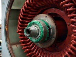
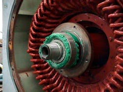
When it is time to relubricate a motor, be sure to add the correct quantity of grease. Excess lubricant is especially harmful because it can increase friction and retain heat. It can also contaminate and deteriorate the motor winding insulation (see Photo 1). Table 1 provides guidelines for grease relubrication quantities and intervals for listed bearings. It also provides formulas for calculating grease quantities for other bearings.
Example. Using the formulas from Table 1, calculate the grease relubrication quantity (G) for a 6324 ball bearing with an outside diameter (D) of 10.24 in. (260 mm) and a width (B) of 2.17 in. (55 mm):
G = 0.11 × 10.24 in. × 2.17 in. = 2.4 fl oz (Imperial)
G = 0.005 × 260 mm × 55 mm = 72 ml (metric)
Relubrication procedure
The following relubrication procedure for ball and roller bearings works best with the motor warm and the shaft stationary. If the motor is running, observe all safety precautions.
- Locate and clean the grease inlet area. If necessary, remove the pipe plug, and install a grease fitting.
- Before removing the relief plug, clean off any caked grease with a wooden stick or suitable tool. If the plug is severely caked with grease, run the motor until the bearing housing is warm enough that grease flows through it freely.
- Add the recommended volume of the recommended lubricant using a hand-operated grease gun.
- Run the motor for 30 minutes with the relief plug removed.
- Replace the relief plug and wipe off any excess grease.
Shielded bearings allow for a “small” amount of relubrication but with little effect, depending on the clearance between the inner race and the shield, which varies from 0.003 in. to 0.015 in. (0.08 mm to 0.38 mm) among manufacturers. Empirical evidence shows some oil from the lubricant will “find its way” into the ball area, but the shield will limit the amount of foreign material that can enter and cause damage. Applying grease externally to the gap enhances the shield’s sealing efficiency.
Oil relubrication frequency, viscosity, and level (quantity) for ball and roller bearings
Relubrication interval
The interval for changing lubricating oils will vary depending on operating conditions, oil quantity, and oil type. In general, replace oil-bath lubricants once a year if the operating temperature is 50°C (120°F) or less. When the operating temperature is 80°C to 100°C (175°F to 210°F), replace the oil at least every three months. For critical equipment, have lubricating oil analyzed at least every three months to determine when replacement is necessary.
Oil level
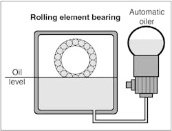
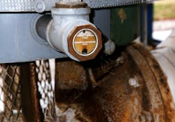
For horizontal shaft applications, maintain the “standstill” oil level on the gauge at approximately the center of the lowest rolling element (see Fig. 2). With vertical shaft applications, about 50% of the rolling elements should be submerged at the “standstill” oil level (see Photo 2 and Fig. 3).
Oil viscosity for horizontal motors
Table 2 provides guidelines for selecting the correct oil viscosity for rolling element bearings in horizontal motors, based on:
Bearing operating temperature (°C or °F).
Bearing pitch diameter (dm = [(ID + OD) ÷ 2] in mm.
Operating speed (n) in rpm
Bearing loading level (light/normal or heavy/impact)
Example. Determine the correct oil viscosity for a 6210 ball bearing operating at 3,600 rpm at 90°C (194°F) under normal loading conditions [i.e., the ratio of the bearing’s dynamic capacity (Cr) to the applied load (Pr) is between 0.06 and 0.12 (0.06 < Cr/Pr < 0.12)].
First, calculate the bearing pitch diameter:
[(ID + OD) ÷ 2] = dm (mm)
[(50 + 90) ÷ 2] = 70 mm
Now determine the dmn value by multiplying the bearing pitch diameter by the operating speed:
dm (mm) x n (rpm) = dmn
70 x 3,600 = 252,000 dmn
The last step is to select the appropriate viscosity from Table 2. In this case, it is ISO VG 56 or VG 68 turbine oil.
Oil viscosity for vertical motors
For vertical motors, use Table 3 on page 18 as a guide for selecting the correct oil viscosity, regardless of bearing size and speed. Note: If the motor lubrication plate specifies synthetic oil, DON’T substitute other oil.
Oil relubrication frequency for sleeve bearings
Bearing clearance and oil viscosity
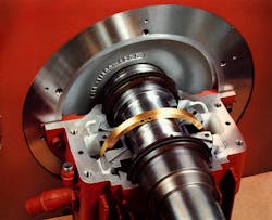
The clearance between the shaft journal and the bearing bore is critical with sleeve bearings such as the one depicted in Photo 3. Any short-term, metal-to-metal contact can increase the bearing temperature, and the associated “wiping” can quickly degrade the bearing, possibly causing catastrophic failure. To maintain sleeve bearing clearances, follow the viscosity guidelines in Table 4.
Relubrication interval
Select relubrication intervals based on the manufacturer’s instructions (if available). Otherwise, use the intervals in Table 4. Frequent starting and stopping, damp or dusty environments, extreme temperatures and other severe service conditions warrant more frequent oil changes than shown in Table 4. Contact the manufacturer regarding oil change intervals for specific situations, or regularly check the oil for contaminants or discoloration and replace it as needed. Another way to determine oil replacement intervals is to have a laboratory analyze oil samples periodically.
Tip: Take oil samples with the motor shut down to avoid removing too much. When replacing the oil, fill the reservoir to the “standstill” level that’s normally shown on the sight glass.
Sleeve bearing oil level
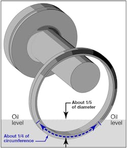
If oil level information is available from the manufacturer, follow it. If not, as a general guideline, the oil rings should be immersed to approximately one-quarter of their circumference or about one-fifth of their diameter (Fig. 4).
If the stationary oil level is too low, it will be dangerously low when some oil is in play (in the bearing, dripping down the inside of the chamber, etc.). If it is too high, the friction between the oil and the rings will increase, so the rings will turn slower and supply less oil to the bearing. Adding oil with the machine at rest is preferable to when it is operating. Overfilling with the machine running can initiate oil siphoning through the labyrinth passages and cause chronic oil leakage.
Finally, note that the recommended temperature limit for all bearings is 80°C (176°F) for normal operation, with the alarm set at 90°C (194°F) and trip at 100°C (212°F).
Thomas H. Bishop, P.E. is a senior technical support specialist at EASA, Inc., St. Louis; (314) 993-2220; www.easa.com. EASA is an international trade association of more than 1,700 firms in nearly 70 countries that sell and service electromechanical apparatus.
About the Author
Tom Bishop, P.E.
Senior Technical Support Specialist
Bishop, P.E., joined the staff of the Electrical Apparatus Service Association (EASA) following more than 30 years of engineering experience at electrical machinery manufacturers and electrical apparatus service firms. Holding a BS in electrical engineering and a professional engineer’s license, Bishop has authored dozens of technical articles and papers as well as presented numerous seminars on electric motor application, maintenance, and repair. He is chairman of EASA’s Technical Services Committee and a principal member of the National Fire Protection Association Electrical Equipment Maintenance Committee (NFPA 70B).
