Selecting Replacement 3-Phase Squirrel Cage Motors

Selection of replacement motors is usually straightforward if the ratings are equivalent. Sometimes, however, a different type of motor is necessary or desirable. For success in these cases, it is essential that the replacement motor provide the required performance — and do so reliably. While this article focuses primarily on the electrical aspects of selecting a 3-phase squirrel cage induction motor (SCIM) replacement for a DC motor or an AC 3-phase synchronous or wound rotor induction motor (WRIM), it also addresses speed and torque considerations.
Replacing A DC Motor with an SCIM and VFD
Historically, the main reason for using a DC motor rather than an AC motor in an application was the need for variable speed. With a DC motor, it’s relatively easy to adjust the speed by varying the armature voltage, and sometimes the field current (field weakening). By contrast, an inherent characteristic of SCIMs operating on 50-Hz or 60-Hz power is almost constant speed, normally varying less than about 5% from no load to full load. (Note: Although WRIMs have variable-speed capabilities and have been available for more than a century, they never came close to rivaling DC motors.)
Advances in variable-frequency drive (VFD) technology have made the combination of a VFD and an SCIM a practical replacement for most applications that formerly used DC motors and drives or motor-generator sets. The VFD varies the frequency, which, in turn, varies the speed of the motor; by varying voltage in proportion to the frequency change, it provides relatively constant motor torque up to the rated line frequency. SCIMs can also operate above rated line frequency at constant power but with proportionately reduced torque.
Regardless of the type of DC motor it replaces, the SCIM must be capable of providing the same speed range and torque characteristics. For example, a suitable replacement for a 75-hp, 1,750/2,500 rpm DC motor would be a 60-Hz, 4-pole (1,800 rpm synchronous speed) SCIM with the same or slightly greater power rating. That would theoretically provide a constant torque characteristic up to about 1,750 rpm.
In this instance, the replacement SCIM would also need to be electrically and mechanically capable of operating at up to 2,500 rpm in a constant power mode, which would require a VFD supply of about 83 Hz. While an inverter duty SCIM rated to 90 Hz would be the usual choice, a constant-speed external fan also may be needed for adequate cooling below 25% of rated speed.
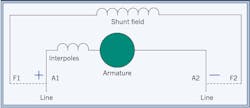
• Replacing a shunt-wound DC motor with an SCIM and VFD
A shunt-wound DC motor (Fig. 1) has relatively constant torque up to its base speed rating. For example, a shunt-wound motor rated 1,750 rpm would have constant torque up to 1,750 rpm. If it were rated 1,750/2,100 rpm, the constant-torque range would extend to 1,750 rpm, above which the motor could produce constant horsepower up to its highest rated speed of 2,100 rpm.
An SCIM has a varying speed-torque curve, and if supply voltage drops during starting due to the locked rotor current, then torque may dip below the values of a shunt motor with the same power rating. This negative feature of operating an SCIM on a utility power supply can be overcome by using a VFD to keep the motor starting current close to rated current.
The type of application also factors into the selection of the replacement SCIM. For example, variable-torque, low-inertia loads, such as pumps, do not require relatively high starting torque capability; thus, an SCIM with the same power rating as the shunt DC motor it is replacing should be sufficient. Other variable-torque loads with high inertia (e.g., fans and blowers) have relatively high starting torque requirements. In such cases, it may be necessary to increase the SCIM power by at least one rating and use a more sophisticated vector VFD. (Note: Shock load applications, such as shredders, may require a VFD with peak current capability that is much higher than standard.)
When converting a constant-torque or high-inertia load application from a shunt DC motor to an SCIM, it is a good practice to verify the motor and drive selection with the VFD and SCIM manufacturers. Some drive manufacturers have downloadable software to aid in the selection of the SCIM and VFD.
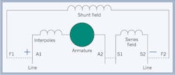
• Replacing a stabilized-shunt or compound-wound DC motor with an SCIM and VFD
Stabilized-shunt motors are relatively weak versions of compound-wound DC motors (Fig. 2) that use a field in series with the armature to increase motor torque. Compound-wound motors can boost torque in response to rapid changes in load, making them difficult to replace with SCIMs. Because such replacements usually require a great deal of engineering by the VFD manufacturer (and possibly the SCIM manufacturer), they are beyond the scope of this article.
AC 3-Phase Motor to SCIM
Replacement of 3-phase AC motors with SCIMs falls into two broad categories: WRIM to SCIM and SCIM to SCIM. Strictly speaking, synchronous motors are WRIMs, but with the synchronous speed capability that WRIMs lack. They also have lower starting torque capability than WRIMs.
• Replacing a 3-phase synchronous motor with an SCIM and VFD
The primary features of synchronous motors include constant speed and the ability to adjust power factor. If the application requires constant speed, an SCIM is not a viable replacement for a synchronous motor because of its inherent slip (i.e., speed changes with load, increasing to near synchronous speed at no load and decreasing to rated speed at rated load).
For example, a 4-pole, 60-Hz AC motor has a synchronous speed of 1,800 rpm. If it is a synchronous motor, it will operate at exactly 1,800 rpm regardless of load (unless severely overloaded). If it is a typical SCIM, its full-load speed rating may be in the range of 1,725 rpm to 1,790 rpm. Although 1,790 rpm is close to 1,800 rpm, it indicates that motor speed will vary from about 1,800 rpm at no load to 1,790 rpm at full load.
The most common SCIMs are NEMA designs A, B, and C, which can have up to 5% slip, and NEMA design D, which can have greater than 5% slip. Even if supplied from a standard VFD, the SCIM may vary slightly in speed, making it unsatisfactory in applications requiring no speed variation regardless of load. One option in such cases would be a vector-type VFD with closed-loop control that can operate the motor at fixed speed with varying load.
• Replacing a WRIM with an SCIM and VFD
A common reason for replacing a WRIM with an SCIM and VFD is to eliminate the maintenance related to slip rings, brushes, external resistance, and associated controls. Many of the application and motor characteristics to consider with such replacements are the same as for DC motors.
WRIMs with secondary resistance provide not only variable speed, but also higher starting torque (up to 300% of rated torque) than most SCIMs. Therefore, it is important to consider the speed-torque characteristics of the load when selecting a replacement SCIM.
With constant-torque loads, for instance, recognize that the SCIM’s varying speed-torque curve may dip below the torque values of a WRIM with the same power rating. For such applications, it’s good practice to select a replacement that is at least one power rating higher. For example, to replace a 60-hp WRIM, select at least a 75-hp SCIM and VFD.
The type of application also factors into the selection of the SCIM. Variable-torque low-inertia loads such as pumps, for example, do not require relatively high starting torque capability, so an SCIM with the same power rating as the original WRIM should be sufficient. Other variable-torque loads with high inertia (e.g., fans and blowers) have relatively high starting torque requirements. Besides increasing the SCIM power by at least one rating, such applications may require a more sophisticated vector VFD.
When converting a constant-torque or high-inertia load application from WRIM to SCIM, it is a good practice to verify the motor and drive selection with the VFD and SCIM manufacturers. Some drive manufacturers have downloadable software to aid in the selection of the SCIM and VFD.
Potential Issues with Speed-Torque and Speed-Current Characteristics
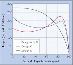
Replacing an SCIM with another SCIM of the same rating should be straightforward, but there are potential pitfalls due to differences in motor designs. NEMA Std. MG 1, 1.18 defines “design” in terms of torque (Fig. 3) and current characteristics and assigns a letter code (A, B, C, or D) to each of four design types (see the Table). Common SCIM nameplate designations for NEMA design letter codes include “Des.,” “NEMA Design,” and “Design.”
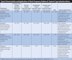
Most 3-phase induction motors are Design B, with comparatively high efficiency and torque characteristics. Although Design A offers higher efficiency, its relatively high starting current can cause nuisance tripping of motor protection circuitry on some applications.
Caution: Letter designations similar to those used for the design codes are used for other motor characteristics. Most notably, the nameplate designation “Code” identifies the locked rotor kVA on a per-horsepower basis by a series of letters from A to V (NEMA MG 1-10.37.2). The farther the code letter is from A, the higher the locked rotor current per hp. A replacement motor with a “higher” code letter may require greater current capacity in upstream electrical equipment (e.g., a larger motor starter). In addition, be aware that insulation class is designated by the letters A, B, F, and H.
Motor Speed-Torque Characteristics
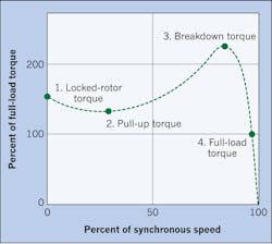
Figure 4 shows an output torque versus speed curve during starting with rated voltage applied for a generic motor (i.e., no specific NEMA design). The motor is not rotating initially (zero speed) and develops locked-rotor torque (1). As with many motor designs, torque dips slightly as the motor accelerates, with the lowest point being the pull-up torque (2). As speed increases further, torque increases to the highest point, which is breakdown torque (3). The speed stabilizes once the motor is loaded to its full-load torque (4). If no load were applied, the motor would attain almost 100% synchronous speed. For example, an unloaded 4-pole, 60-Hz motor might reach 1,799 rpm, which is almost its synchronous speed of 1,800 rpm.
Motor Speed-Torque and Speed-Current Characteristics
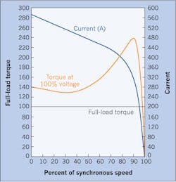
Manufacturer information for motors often presents torque values as a percent of rated torque. For example, consider a 30-hp, 4-pole, 60-Hz, Design B motor with a full-load speed of 1,760 rpm, full-load torque (FLT) of 90 lb-ft, locked-rotor torque (LRT) of 126 lb-ft, pull-up torque (PUT) of 112 lb-ft, and breakdown torque (BDT) of 216 lb-ft. Expressed as percent the torque values are: LRT 140% [(126/90) × 100], PUT 124% [(112/90) × 100], and BDT 240% [(216/90) × 100]. Figure 5 illustrates the speed-torque and speed-current characteristics for this motor.
One common misapplication is the attempt to replace a Design C or D motor with a Design B. The unfortunate outcome is usually that the Design B motor, with its lower starting torque (Fig. 6), cannot accelerate the load to operating speed. The resulting high starting current may overheat the motor winding, tripping overcurrent or over temperature detectors or causing the winding to fail.

Motor Selection Examples
Figure 6 illustrates the speed-torque curve for a motor that has been properly selected for an application. Note that at any speed point the motor torque (TM) exceeds the load torque (TL) at that point, with the difference designated as the torque available (TA).

Figure 7 is similar to Fig. 6, except that this motor is poorly matched to the application. Note that at startup the TL exceeds the TM, leaving no torque available TA to rotate the motor and accelerate the load. Absent quick-acting motor protection, the motor winding could overheat and fail. Figure 7 also highlights another failure-to-perform scenario at the point along the speed-torque curves where TL exceeds TM. The resulting negative TA condition will prevent further acceleration, while the motor current will still be near the locked-rotor level. Unless motor protection responds swiftly, the winding will overheat and fail.
Bishop is a senior technical support specialist at EASA in St. Louis, Mo. EASA is an international trade association of nearly 1,800 firms in about 80 countries that sell and service electromechanical apparatus. Contact him at [email protected].
About the Author
Tom Bishop, P.E.
Senior Technical Support Specialist
Bishop, P.E., joined the staff of the Electrical Apparatus Service Association (EASA) following more than 30 years of engineering experience at electrical machinery manufacturers and electrical apparatus service firms. Holding a BS in electrical engineering and a professional engineer’s license, Bishop has authored dozens of technical articles and papers as well as presented numerous seminars on electric motor application, maintenance, and repair. He is chairman of EASA’s Technical Services Committee and a principal member of the National Fire Protection Association Electrical Equipment Maintenance Committee (NFPA 70B).