Instead of two Divisions, Art. 505 provides three Zones (see Division vs. Zone). Because the Zone system breaks things down differently from the way the Division system does, it may better suit a given area.
Another big difference is Art. 505 has documentation requirements [505.4(A)]. The NEC doesn’t detail these, but the informational note names standards that have examples. The NEC also provides an extensive listing of reference standards [505.5(B)] that can help you correctly apply the rules of Art. 505.
Classification
Among the hazardous location Articles, only Art. 500 and Art. 505 have classification requirements [500.5 and 505.5, respectively]. Much of the text and informational notes in 505.5 are also found verbatim in 500.5. However, two key differences in how 500.5 and 505.5 present classification requirements are:
1) 500.5 addresses Class I, II, and III locations while 505.5 addresses only Class I [505.5(B)].
2) 500.5 addresses the Division system while 505.5 addresses the Zone system.
Material groups
When applying the rules of Art. 501, you use the material group requirements of 500.6, but Art. 505 has its own material group requirements [505.6]. They differ greatly:
• Art. 500 covers Class I, Group A, B, C, and D materials [500.6(A)], and Class II Group E, F, and G materials [500.6(B)].
• Art. 505 covers Class I Group IIA, IIB, and IIC materials [505.6].
The basis for Art. 505 material groupings is risk, not volatility. The degree of risk is a factor of the maximum experimental safe gap, minimum igniting current, or both. As the group letter goes up, so does the risk associated with gases in that group. But this presents an interesting little problem that may lead to confusion. See if you can spot what it is:
• 505.6(A). Group IIC. Very high risk.
• 505.6(B). Group IIB. High risk.
• 506.6(C) Group IIA. Moderate risk.
The NEC presents the groups in decreasing order of risk, but names them with letters in ascending order. Consequently, A and C are transposed in the subsection headings vs. the group name. Just be aware of that so you don’t inadvertently swap things in your mind.
If enough of a particular gas is present to pose a combustion risk, it can determine the grouping. The atmosphere grouping is based on the gas with the highest risk — not which gas is present in greatest volume.
Flexibility at a cost
The Zone system gives you flexibility over the Division system, but it imposes additional requirements, such as:
• Extraordinary care with regard to installation and maintenance [505.7 Informational Note 1].
• Special consideration for low ambient conditions [505.7 Informational Note 2].
• Class I, Zone 2 locations cannot overlap Class I, Div. 2 locations.
• Class I, Zone 0 or 1 locations cannot even abut Class I, Div. 1 locations [505.7(A)].
Only qualified persons [Art. 100] may classify areas, perform engineering and design, select equipment, select wiring methods, install, or inspect [505.7(A)]. That requirement applies to hazardous locations generally; it really belongs in Art. 500.
These disparate and specialized functions typically require several individuals for the qualified person criterion to be met. The hazardous location game is a team sport.
Protection techniques
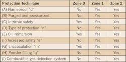
Yet another big difference between Art. 501 and Art. 505 is Art. 505 has nine permitted protection techniques [505.8(A) - (I)]. The definitions for these are in 505.2. The Table helps you quickly see which protection techniques apply to which Zones.
An important fact that’s hard to spot in the NEC text is easy to spot in the Table: All of the protection methods apply to Zone 1 and Zone 2, but only two of them also apply to Zone 0.
You can use intrinsically safety systems (covered in the September 2013 issue of EC&M) and oil immersion, regardless of Zone. You can’t use any other techniques for Zone 0.
Me, my zone, and I
Unlike the other 505.8 subsections, 505.8(I) doesn’t explicitly say which Zones it applies to. So how do we know it doesn’t apply to Zone 0, other than the fact it mentions only Zones 1 and 2?
A Zone 0 location is one in which the combustible gases are present continuously or for long periods, so a detector is superfluous. With Zones 1 and 2, the detector can tell you something has changed.
The actual protection comes from implementing the additional requirements in 505.8(I). You can use this method only in industrial establishments with restricted public access and where only qualified people maintain the equipment. Extensive documentation for maintenance and supervision is also required. Three additional requirements are as follows:
1) If a location is classified as Class I, Zone 1 due to inadequate ventilation, the combustible gas detection equipment must be listed for Class I, Zone 1. It must also be listed for the appropriate material group and for the detection of the specific gas(es) in question [505.8(I)(1)].
2) The requirements above also apply to the interior of a control panel containing instrumentation that uses or measures flammables and where you are using electrical equipment suitable for Class I, Zone 2 [505.8(I)(3)].
3) You can use electrical equipment for unclassified locations in a building inside (or opening into) a Class I, Zone 2 location if that building doesn’t contain the source of the flammable gas or vapor. The combustible gas detection equipment must be listed for Class I, Zone 1 or Zone 2. It must also be listed for the appropriate material group and for the detection of the specific gas(es) in question [505.8(I)(2)].
Equipment
Subsection 505.9 is long and highly detailed. Fortunately for the installer, most of this information is for the manufacturer.
You need to ensure the equipment you use is listed or labeled for the application and bears evidence of evaluation from a qualified testing lab or inspection agency. You also need to evaluate the temperature per 505.9(D). Your electrical distributor can help you comply with these requirements.
The equipment must be designed for threaded raceway rather than electrical tubing. Conduit and fittings must be threaded and wrenchtight [505.9(E)(1)]. All unused openings in electrical panels and boxes must be closed [110.12(A)], but with this equipment you must close those openings with threaded plugs listed for the location [505.9(E)(3)].
Wiring methods
Different wiring methods are permissible in different Zones:
Zone 0. Only intrinsically safe wiring methods permitted [505.15(A)].
Zone 1. You can use intrinsically safe, and/or any of several other wiring methods. These include Type MI Cable, Type RMC, Type PVC, and Type RTRC [505.15(B)].
Zone 2. You can use any wiring method suitable for Zone 1. Additional choices include Type MC Cable, Type ITC Cable, and Type PLTC Cable (there are many more) [505.15(C)].
Seals
Seals don’t have to be explosionproof or flameproof, but you must use them on cables, in conduit, and in enclosures. The requirements are highly detailed, so review 505.16 prior to doing the installation work. Note that using seals may affect your conduit sizing because the cross-sectional area of the conductors permitted in a seal can’t exceed 25% of the cross-sectional area of the conduit unless the seal is specifically listed for a higher fill percentage [505.16(D)(5)].
Grounding and bonding
In addition to complying with Art. 250 requirements, you must maintain the bonding path integrity by using bonding jumpers:
• Around bushings (don’t rely on the bushing) [505.25(A)]
• Inside flexible raceway (don’t rely on the jointed metal jacket) [505.25(B)].
Process sealing
These are the same as the requirements for Class I locations [501.17]. They’re new in Art. 501 with the 2011 NEC, but already existed in Art. 505 in the 2008 NEC. They haven’t changed with the 2011 revision.
We noted in our coverage of Art. 501 (“Article 501: Class I Hazardous Locations,” June 2013 issue of EC&M) that, “A process seal prevents process fluids from migrating into the electrical system. If process-connected electrical equipment incorporates only a single process seal, you must provide an additional barrier (in case the seal fails). If the equipment does not rely on a single seal, then you don’t need to do anything extra.”
Staying in the Zone
One cause of inspection failures is the use of an inappropriate protection technique. To avoid making this error, remember that only two of the permissible techniques apply to Zone 0. You can use intrinsic safety systems anywhere, and the same goes for encapsulation. Don’t use any other method in a Zone 0 location, and you’ll be safe from making protection technique applicability errors.
Lamendola is an electrical consultant located in Merriam, Kan. He can be reached at [email protected].
SIDEBAR: Division vs. Zone
The NEC provides more precise and detailed definitions of Divisions and Zones, but this thumbnail comparison will help you understand the essential differences.
In the Division classification system [501.5(B)], combustibles are present under:
• Normal conditions: Div. 1.
• Abnormal conditions: Div. 2:
In the Zone classification system [505.5(B)], combustibles are:
• Present continuously or for long periods: Zone 0.
• Likely to be present or are frequently (but not continuously) present under normal conditions: Zone 1.
• Present only under abnormal conditions or only for short periods: Zone 2.
About the Author

Mark Lamendola
Mark is an expert in maintenance management, having racked up an impressive track record during his time working in the field. He also has extensive knowledge of, and practical expertise with, the National Electrical Code (NEC). Through his consulting business, he provides articles and training materials on electrical topics, specializing in making difficult subjects easy to understand and focusing on the practical aspects of electrical work.
Prior to starting his own business, Mark served as the Technical Editor on EC&M for six years, worked three years in nuclear maintenance, six years as a contract project engineer/project manager, three years as a systems engineer, and three years in plant maintenance management.
Mark earned an AAS degree from Rock Valley College, a BSEET from Columbia Pacific University, and an MBA from Lake Erie College. He’s also completed several related certifications over the years and even was formerly licensed as a Master Electrician. He is a Senior Member of the IEEE and past Chairman of the Kansas City Chapters of both the IEEE and the IEEE Computer Society. Mark also served as the program director for, a board member of, and webmaster of, the Midwest Chapter of the 7x24 Exchange. He has also held memberships with the following organizations: NETA, NFPA, International Association of Webmasters, and Institute of Certified Professional Managers.


