Article 110 of the National Electrical Code (NEC) covers the general requirements for the examination and approval, installation and use, access to, and spaces about electrical equipment. Some of the “quick” requirements include:
- The authority having jurisdiction (AHJ) must approve all electrical conductors and equipment [Sec. 110.2].
- Equipment that is listed and/or labeled must be installed and used per instructions in the listing or labeling requirements [Sec. 110.3(B)].
- Connectors are listed for a specific number and size of cables.
- The circuit nominal system voltage cannot exceed the rating of the equipment [Sec. 110.4].
- Electrical installations must be free from short circuits, ground faults, or connections to conductive metal parts unless required or permitted by the Code [Sec. 110.7].
- The only wiring methods permitted by the NEC are those in the NEC [Sec. 110.8]
Interrupting or Short-Circuit Rating
Be careful not to confuse the term “interrupting rating” [Sec. 110.9] with “short-circuit current rating” [Sec. 110.10].
Overcurrent protective devices must have an interrupting rating capacity equal to or greater than the fault current available at the equipment line terminals [Sec. 110.9]. Unless marked otherwise, the ampere interrupting capacity (AIC)rating for circuit breakers is 5,000A [Sec. 240.83(C)], and it is 10,000A for fuses [Sec. 240.60(C)(3)].
Electrical equipment must have a short-circuit current rating (SCCR) that permits the circuit protective device to open due to a short circuit or ground fault without extensive damage to the electrical equipment [Sec. 110.10]. Listed equipment applied per its listing meets this requirement (Fig. 1).
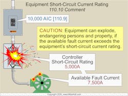
Fig. 1. Electrical equipment must have a short-circuit current rating (SCCR) that permits the circuit protective device to open due to a short circuit or ground fault without extensive damage to the electrical equipment.
Available short‑circuit current is the current, in amperes, available at a given point in the electrical system. This current is first determined at the secondary terminals of the serving electric utility transformer. Thereafter, the available short‑circuit current is calculated at the terminals of the service disconnect, then panelboards and other equipment as various connections are made downstream from the main service. Beginning at the serving electric utility transformer, the available short‑circuit current decreases at each downstream connection point of the electrical system.
Work Quality
Electrical equipment and cabling must be installed in a neat and workmanlike manner [Sec. 110.12]. One aspect of this is that unused openings must be closed by fittings that provide protection substantially equivalent to the wall of the equipment [Sec. 110.12(A) and (C)].
Exposed cables must be supported by the structural components of the building so that the cable will not be damaged by normal building use. Electrical equipment must be firmly secured to the surface on which it is mounted [Sec. 110.13].
Conductor terminal and splicing devices must be identified for the conductor material, and they must be properly installed and used per the manufacturer’s instructions [Sec. 110.3(B)].
Single direct burial types UF or USE conductors can be spliced underground with a device that is listed for direct burial [Sec. 300.5(E) and Sec. 300.15(G)]. Multiconductor UF or USE cables can have the individual conductors spliced underground with a listed splice kit that encapsulates the conductors and cable jacket.
Electrical connection failures cause insulation failure, short circuits, ground faults, and fires. Improper terminations, poor workmanship, violating the manufacturer’s instructions, and improper torqueing can each cause poor electrical connections.
Conductor Ratings
For equipment rated 100A or less, size conductors 1 AWG and smaller per the ampacities in the 60°C temperature column of Table 310.16 [Sec. 110.14(C)(1)(a)(1)]. Conductors rated for at least 75°C temperature and that terminate on terminals rated 75°C can be sized per the ampacities in the 75°C temperature column of Table 310.16 [Sec. 110.14(C)(1)(a)(3)].
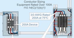
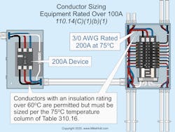
For equipment rated greater than 100A, size the conductor per the ampacities in the 75°C temperature column of Table 310.16 [Sec. 110.14(C)(1)(b)(1)] (Fig. 2). Splicing and terminating devices with terminals rated 90°C and not connected to electrical equipment can have their conductors sized per the ampacities in the 90°C temperature column of Table 310.16 [Sec. 110.14(C)(2)].
Markings
You’ll find many requirements for markings throughout Art. 110. For example, where caution, warning, or danger labels are required, the labels must meet three requirements [Sec. 110.21(B)]:
1. The markings must warn of the hazards using effective words, colors, symbols, or a combination of words, colors, and symbols.
2. The label cannot be handwritten, and it must be permanently affixed to the equipment.
3. The marking must be of sufficient durability to withstand the environment involved.
Some other marking requirements include:
- For each disconnect, its purpose [Sec. 110.22(A)].
- High leg conductor [Sec. 110.15].
- Arc flash hazard warning [Sec. 110.16(A)].
- Service disconnect, available fault current [Sec. 110.24(A)].
Space about equipment, 1,000V or less
Spaces about electrical equipment consist of working space for worker protection [Sec. 110.26(A)] and dedicated space to provide access to, and protection of, equipment [Sec. 110.26(E)]. The working space must always be clear; therefore, this space cannot be used for storage [Sec. 110.26(B)]. Working space is not required at the back or sides of equipment where all connections and all renewable, adjustable, or serviceable parts are accessible from the front of the equipment.
While OSHA and NEC tables provide values for various voltages and conditions, these are minimum values. The actual values needed for adequate working space and worker protection in each installation may be greater. NFPA 70E, Standard for Electrical Safety in the Workplace, provides guidance in determining the severity of potential exposure, planning safe work practices — including establishing an electrically safe work condition — arc flash labeling, and selecting personal protective equipment (PPE).
The point of determining the correct working space for a given installation isn’t to see how little of it you can get by with. The point is to determine how much is needed to efficiently and safely service the equipment. The efficiency aspect isn’t required by OSHA or the NEC, but it can dramatically affect operational profitability. This same logic applies to Part III of Art. 110, which provides working space requirements for installations over 1,000V.
You must allow for sufficient depth, width, and height:
- When you measure the depth of a working space, do so from the enclosure front, not the live parts [Sec. 110.26(A)(1)].
- The width of the working space must be a minimum of 30 in., but in no case less than the width of the equipment. You can measure the width from left to right, from right to left, or simply centered on the equipment. It can overlap the working space for other electrical equipment. The working space must be of sufficient width, depth, and height to permit equipment doors to open at least 90° [Sec. 110.26(A)(2)].
- The height of the working space must be clear and extend from the grade, floor, or platform to a height of 6½ ft or the height of the equipment. Electrical equipment such raceways, cables, wireways, or panelboards or support structures (for example, concrete pads) can’t extend more than 6 in. beyond the front of the electrical equipment [Sec. 110.26(A)(3)] (Fig. 3).
Exception No. 1: The minimum height of working space does not apply to a service disconnect or panelboards rated 200A or less located in an existing dwelling unit.
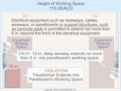
Fig. 3. The height of the working space must be clear and extend from the grade, floor, or platform to a height of 6½ ft or the height of the equipment.
Exception No. 2: Meters are permitted in the working space.
If equipment that’s above a suspended ceiling or in a crawl space is likely to require servicing while energized, all of these conditions apply [Sec. 110.26(A)(4)]:
(1) Equipment above a suspended ceiling must have an access opening at least 22 in. × 22 in. Equipment in a crawl space must have an accessible opening at least 22 in. × 30 in.
(2) The working space width must be at least 30 in., but never less than the width of the equipment.
(3) The working space must permit equipment doors to open 90°.
(4) The working space in front of the equipment must comply with the depth requirements of Table 110.26(A)(1); horizontal ceiling structural members are permitted in this space.
When live parts are exposed for inspection or servicing, the working space, if in a passageway or open space, must be suitably guarded. Furthermore, at least one entrance must provide access to and egress from the working space. [Sec. 110.26(C)].
Avoiding Art. 110 Violations
Thinking that you can just look up something from here if a question arises is a mistake. To avoid errors, allot time on a regular basis to study, understand, and be familiar with the requirements.
Working space issues are especially an area of confusion. Remember, nothing prevents you from exceeding working space minimums if conditions merit doing so. You just can’t go the other direction.
These materials are provided to us by Mike Holt Enterprises in Leesburg, Fla. To view Code training materials offered by this company, visit www.mikeholt.com/code.

About the Author

Mike Holt
Mike Holt is the owner of Mike Holt Enterprises (www.MikeHolt.com), one of the largest electrical publishers in the United States. He earned a master's degree in the Business Administration Program (MBA) from the University of Miami. He earned his reputation as a National Electrical Code (NEC) expert by working his way up through the electrical trade. Formally a construction editor for two different trade publications, Mike started his career as an apprentice electrician and eventually became a master electrician, an electrical inspector, a contractor, and an educator. Mike has taught more than 1,000 classes on 30 different electrical-related subjects — ranging from alarm installations to exam preparation and voltage drop calculations. He continues to produce seminars, videos, books, and online training for the trade as well as contribute monthly Code content to EC&M magazine.