NEC Requirements for Grounding Electrode Systems
Based on the 2020 NEC.
The grounding electrode provides the essential function of connecting the electrical system and electrical equipment to the earth. In some cases, the grounding electrode(s) serves to ground both the electrical system and the equipment to earth (grounded system). In other cases, the grounding electrode only connects the equipment to the earth (ungrounded system). In both situations, the primary purpose of the grounding electrode(s) is to maintain the electrical equipment at the earth’s potential present where the grounding electrode(s) is located. The earth’s potential is assumed to be zero.
Another function of the grounding electrode(s) is to dissipate overvoltage into the earth. Overvoltages can be caused by high-voltage conductors being accidentally connected to the lower-voltage system, such as by an internal failure in a transformer or by an overhead conductor dropping on the lower-voltage conductor. Overvoltage can also be caused by lightning.
In today’s homes, appliances containing microprocessors have become increasingly prevalent. Section 250.24(D) requires “… the equipment grounding conductors, the service-equipment enclosures, and, where the system is grounded, the grounded service conductor to be connected to the grounding electrode(s) required by Part III…” of Art. 250.
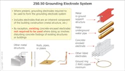
Section 250.50 requires that all grounding electrodes that are present at each building or structure served be bonded together to form the grounding electrode system. This generally means that where metallic water piping meeting the requirements of Sec. 250.52(A)(1), metallic in-ground support structure meeting the requirements of Sec. 250.52(A)(2), or a concrete-encased electrode meeting the requirements of Sec. 250.52(A)(3) is part of the construction of the building or structure, it is used as part of the grounding electrode for the electrical system (Fig. 1).
Items prohibited as grounding electrodes
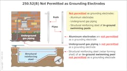
There are some things that cannot be used or are prohibited from being used as grounding electrode(s), as shown in Fig. 2. This may not have always been true in earlier editions of the NEC. For the 2020 edition of the NEC, the following three items are prohibited from being used as a grounding electrode:
- Underground metal gas piping systems are not permitted to be used as grounding electrodes. This does not eliminate the requirement that metal gas piping systems installed in or on buildings or structures be bonded.
- Conductive objects made from aluminum also are not permitted to be used because aluminum would corrode in many types of soil and become ineffective as an electrode.
- The metallic elements making up a swimming pool shell or frame are not to be used as a grounding electrode for the premise’s power system.
An electrode typically installed by electrical installer
This article cannot cover all the various grounding electrodes, so let’s discuss a particular type installed by an electrical professional. As previously stated, the water pipe, in-ground support structure, and concrete-encased electrodes are installed by other trades. Where electrodes that are described in Sec. 250.52(A)(1) through (A)(7) do not exist at the building or structure served, a grounding electrode or electrode system is required to be installed and utilized.
Let’s briefly discuss rod and pipe electrodes. Section 250.52(A)(5) requires that these electrodes not be less than 2.44 m (8 ft) in length and consist of the following materials:
- Pipe or conduit not to be smaller than metric designator 21 (trade size ¾) and, where made of steel, to have the outer surface galvanized or otherwise metal-coated for corrosion protection.
- Rod-type to be of stainless, copper, or zinc-coated steel and at least 15.87 mm (5/8 in.) in diameter unless listed.
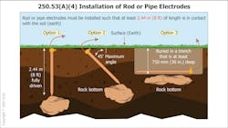
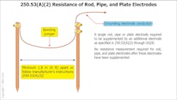
Section 250.53(A) requires rod and pipe electrodes to be installed in contact with the soil at least 2.44 m (8 ft). They are to be driven vertically unless a rock bottom is encountered. If rock bottom is encountered that prevents the rod from being driven 8 ft vertically, it is permitted to be installed at an oblique angle of not more than 45º from vertical. Where a rock bottom is encountered at an angle up to 45º, which prevent the rod from being installed, only then can the rod or pipe be buried in a trench that is at least 750 mm (30 in.) deep, as seen in Fig. 3.
The upper end of the rod is to be flush with or below ground level unless the aboveground end of the rod, and the grounding electrode conductor attachment is protected from physical damage. This will require that a ground rod longer than 8 ft be used if any part of the rod is exposed above ground level. Since an 8-ft ground rod or pipe must be driven the entire length, the ground clamp is required to be listed for direct earth burial.
Where more than one of the rods is installed to form a grounding electrode system, Sec. 250.53(B) requires that spacing between them be a minimum of 1.83 m (6 ft). This minimum spacing is to ensure both electrodes provide a connection to the earth without interfering with each other. While this spacing is the NEC minimum, other standards such as IEEE recommend the minimum spacing of rods be at least equal to the depth the electrode is driven.
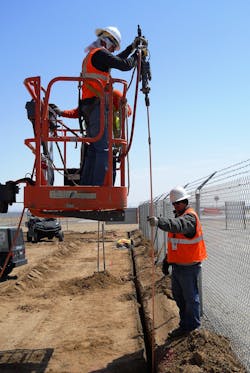
As can be seen by the intro photo, driving ground rods can be difficult work depending on what part of the country you are located in. Installation of these components of a grounding system needs to be done correctly and in compliance with the NEC. The safety of the building or structure depends on you.
Joseph Wages, Jr., is the director of digital education for IAEI. He represents IAEI on NFPA’s NEC Code Making Panel-2 for the 2020 NEC. He also serves on the UL Electrical Council and on several UL Technical Standard Panels. Wages, Jr., is an ICC certified building official and an IAEI certified electrical inspector for one- and two-family dwellings. He can be reached at [email protected].
Inspector Intel articles are provided by the International Association of Electrical Inspectors (IAEI), www.iaei.org, a membership-driven, non-profit association headquartered in Richardson, Texas, that promotes electrical safety throughout the industry by providing education, certification of inspectors, advocacy, partnerships, and expert leadership in electrical codes and standards.
About the Author
Joseph Wages, Jr.
Joseph Wages, Jr., is the director of education with IAEI. Previously, he held the positions of technical advisor, education, codes and standards and seminar coordinator at IAEI. He represents IAEI on NFPA’s NEC Code Making Panel-14 for the 2026 NEC. He previously represented IAEI on NFPA’s NEC Code Making Panel-2 for the 2020 and 2023 NEC code cycles and NFPA’s NEC Code Making Panel-3 for the 2014 and 2017 NEC.
He serves on the Underwriters Laboratories (UL) Electrical Council and on several UL Technical Standard Panels. Joseph continues to hold state electrical licenses and several IAEI and ICC building related certifications. Joseph can be reached at [email protected].