Top 25 Changes to the 2026 National Electrical Code
Key Highlights
- The 2026 NEC features more than 3,900 public inputs, leading to substantial reorganizations, new Articles, and enhanced clarity for electrical professionals.
- Key updates include expanded GFCI protection requirements, new rules for electric vehicle supply equipment (EVSE), and revised service disconnect location and marking standards.
- New provisions address the integration of sustainable technologies, such as electric vehicles and energy management systems, reflecting industry trends and future demands.
- Preparations for the 2029 NEC include structural revisions and increased emphasis on engineered designs for complex systems, ensuring ongoing safety and compliance.

The 2026 National Electrical Code (NEC) marks another year of significant evolution for the electrical industry. With 3,933 public inputs, 1,507 first revisions, 1,800 public comments, 894 second revisions, 239 first/second correlating revisions, and 63 certified amending motions, this latest edition of the Code brings substantial reorganizations, new Articles, and dozens of additional Sections designed to improve clarity and usability.
Why do these changes matter? For electrical professionals who are expected to know the NEC inside and out, it’s important to realize these changes are more than merely administrative. They mirror broader trends shaping the industry, including a continued emphasis on safety, the integration of sustainable technologies, and the adoption of forward-looking practices. For example, expanded GFCI protection requirements underscore the ongoing focus on reducing electric shock hazards, while other changes reflect the growing role of electric vehicles, limited-energy systems, and high-voltage installations in today’s electrical landscape. By embracing these updates, electrical professionals can maintain the highest standards of safety while positioning themselves to meet tomorrow’s technical demands.
In addition to the online and print article outlining the most important changes to the 2025 NEC, EC&M has a downloadable PDF of this entire article available to save, print, review, and keep on hand for your reference.
Across-the-board changes
Before we dive into the Top 25 changes to the 2026 NEC, there are several global updates worth noting. The term “overcurrent protective device” was replaced with the acronym “OCPD,” reducing repetitive text while standardizing terminology. The term “overcurrent device” was also updated to overcurrent protective device (OCPD). Similarly, the designation “AC” was added to rules that only apply to alternating-current circuits, clarifying that these requirements do not extend to DC systems.
Many Articles in the 2026 NEC are either new, relocated, or deleted. For specifics on the revisions in these areas, see the Sidebars (New, Relocated, or Renamed Articles; Limited-Energy Systems Articles; New Articles Over 1,000VAC or 1,500VDC; and Deleted Articles below).
Looking ahead to 2029
The 2026 NEC also previews structural revisions anticipated for the 2029 edition. Informative Annex L provides a clear picture of proposed structural changes and highlights updates made during the 2026 cycle. NFPA has created a dedicated webpage to outline the impact of these revisions and provide a platform for public feedback.As you read through the analysis on each of the following changes, please note that the blue underlined text is NEW to the Code. Although it is slightly reworded or shortened from the actual text shown in the NEC, it’s a good representation of the intent of the real rule change.
Change #1
NEW
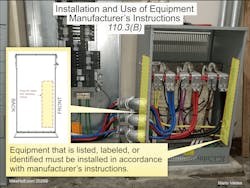
Section 110.3(B) Manufacturer’s Instructions
Analysis of the change:
A manufacturer’s installation instructions cannot conflict with the NEC requirements. The instructions can exceed the NEC (where specified by the manufacturer), but you can never reduce the requirements of the Code.
(B) Installation and Use. Equipment that is listed, labeled, or identified must be installed in accordance with manufacturer’s instructions, as shown in Fig. 1.
New or revised Code language:
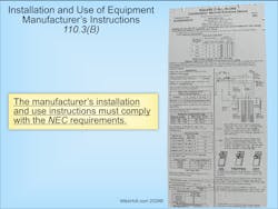
The manufacturer’s installation and use instructions must comply with NEC requirements (Fig. 2).
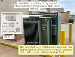
Note: The manufacturer’s installation instructions can be provided as printed material, quick response (QR) code, or web address to download (Fig. 3).
Author’s comment:
Many electricians throw away installation instructions, but this is no longer a viable reason for not having access to them. Because manufacturers now use QR codes on electrical equipment, the instructions are always readily available on their websites.
Change #2
EXPANDED
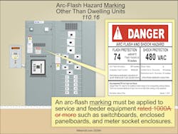
Section 110.16 Arc Flash Hazard Marking, Other Than Dwelling Units
Analysis of the change:
Arc flash warning label requirements for non-dwelling unit service and feeder equipment were significantly expanded by deleting a few words. The previous Code only required arc flash warning labeling of service and feeder equipment of 1,000A or more. Now it’s required for all non-dwelling distribution equipment, and the arc flash label must include specific information (such as the date the arc flash assessment was completed).
New or revised Code language:
In other than dwelling units, a permanent arc flash marking must be applied to service and feeder equipment rated 1,000A or more such as switchboards, enclosed panelboards, and meter socket enclosures (Fig. 4).
Author’s comment:
An arc flash event can reach temperatures of 35,000°F, which turns metal from a solid to gas vapors. This releases molten shrapnel that pierces the skin, causing severe burns — or even death. The reason the arc flash label is not required in dwelling units is the nominal voltage will be single-phase, 120V line-to-ground (240V line-to-line), so the arc fault will self-extinguish with every zero crossing of the sinusoidal waveform. A 3-phase arc fault is sustainable in accordance with IEEE-1584.
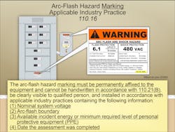
The arc flash hazard marking must be permanently affixed to the equipment and cannot be handwritten in accordance with Sec. 110.21(B), be clearly visible to a qualified person, and be installed in accordance with applicable industry practices containing the following information:
(1) Nominal system voltage
(2) Arc flash boundary
(3) Available incident energy or minimum required level of personal protective equipment (PPE)
(4) Date the assessment was completed (Fig. 5)
Note 2: NFPA 70E, Standard for Electrical Safety in the Workplace, provides applicable industry practices for developing arc flash equipment markings that include nominal system voltage, incident energy levels, arc flash boundaries, and by selecting an appropriate level of personal protective equipment.
Change #3
NEW
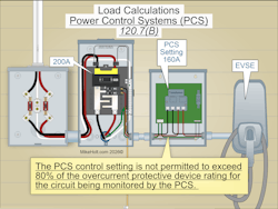
Section 120.7(B) Power Control Systems (PCSs)
Analysis of the change:
For load calculations, we can use a listed PCS with a control setting not exceeding 80% of the overcurrent protective device. This prevents overload of the branch-circuit, feeder, or service conductors. Controlling loads with a PCS avoids an expensive upgrade if your panel or service is near capacity.
New or revised Code language:
(B) PCS Control Setting. When used in load calculations, the control setting is not permitted to exceed 80% of the overcurrent protective device rating for the circuit being monitored by the PCS (Fig. 6).
Change #4
NEW
Section 120.7(C) Power Control Systems (PCSs)
Analysis of the change:
A new rule clarifies how to calculate loads monitored and managed by a power control system (PCS) by distinguishing between controlled and non-controlled loads. This provides clearer direction when sizing loads with PCS technology. An Informational Note was added to give examples of how load calculations should be handled when a PCS is used to manage connected loads.
New or revised Code language:
(C) Load Calculations Using PCS. The load on the branch circuit, feeder, or service must be the sum of the controlled loads. Controlled loads are determined in Sec. 120.7(C)(1), and noncontrolled loads are determined in Sec. 120.7(C)(2).
(1) Controlled Loads. Controlled loads must be based on the monitoring by the PCS to provide overload control. The PCS control configuration must comply with one or both of the following:
(1) If the PCS monitors only controlled loads, the control setting must be used in place of the controlled loads in load calculations.
(2) If the PCS monitors both controlled and noncontrolled loads, the minimum operating current of the controlled loads must be used in place of the controlled loads in load calculations.
Note: Minimum operating current is a value greater than or equal to zero representing the minimum current of the controlled loads.
(2) Noncontrolled Loads. Load calculations for loads not controlled by the PCS must comply with Art. 120, Parts II through VII.
Note: See Informative Annex D Examples D14(a) through D14(d) for examples of load calculations with loads managed by PCSs.
Change #5
NEW
Section 120.82(B) General Lighting Demand, First 8kVA
Analysis of the change:
The demand load for optional dwelling unit load calculations was reduced from the first “10kVA” at 100% to the first “8kVA” at 100%. The effect is a slightly smaller demand load — the treatment of the first 10kW of load at 100% is reduced.
New or revised Code language:
(B) General Loads. The demand load must not be less than 100% of the first 8kVA, plus 40% of the remaining kVA for the following loads.
Change #6
NEW
Section 120.82(B) General Lighting Load, 2VA
Analysis of the change:
Based on studies by the Department of Energy, the general lighting and receptacle load in a dwelling unit was reduced from “3VA” to “2VA” per square foot for feeder/service load calculations.
New or revised Code language:
(1) General Lighting. The general lighting load is based on 2VA per sq ft for general lighting and general-use receptacles. The sq ft area is determined in accordance with Sec. 120.5(C).
(2) Small-Appliance and Laundry Circuits. Add 1,500VA for each 20A small-appliance circuit required by Sec. 210.11(C)(1)(a) with a minimum of two circuits per dwelling unit, and 1,500VA for each 20A laundry circuit required by Sec. 210.11(C)(2), with a minimum of one circuit per dwelling unit.
(3) Appliances. The nameplate rating of the following appliances:
a. Appliances that are fastened in place, permanently connected (hard-wired), or located on a specific circuit
b. Ranges, wall-mounted ovens, and counter-mounted cooking units
c. Clothes dryers that are not connected to the laundry branch circuit
d. Water heaters
(4) Motor VA. The nameplate ampere or kVA rating of all permanently connected motors not included in Sec. 120.82(B)(3).
(C) Air-Conditioning and Heating Equipment. The larger of Sec. 120.82(C)(1) through (6):
(1) Air-Conditioning Equipment. Use 100% of the air-conditioning nameplate ratings.
(2) Heat-Pump Compressor without Supplemental Heating. Use 100% of the heat-pump nameplate rating.
(3) Heat-Pump Compressor with Supplemental Heating. Use 100% of the nameplate rating of the heat pump, and use 65% of the supplemental electric heating for central electric space-heating systems.
(4) Space-Heating Units (Three Units or Less). Use 65% of the nameplate ratings.
(5) Space-Heating Units (Four or More Units). Use 40% of the nameplate ratings.
(6) Electric Thermal Storage and Other Heating. Use 100% of the nameplate rating.
Change #7
NEW
Section 120.82(D) Electric Vehicle Supply Equipment Load at 100%
Analysis of the change:
For the dwelling unit optional method, the electric vehicle supply equipment (EVSE) load is required to be calculated at 100% with no demand factor because it represents a significant load.
New or revised Code language:
(D) Electric Vehicle Supply Equipment (EVSE). Use 100% of the electric vehicle supply equipment nameplate rating in accordance with Sec. 120.57.
Change #8
NEW
Section 130.50 General
Analysis of the change:
Power control system (PCS) requirements were added to a new Part II of Art. 130. There are two types of energy management systems (EMSs). A traditional EMS monitors energy usage and control loads to save money. Power control systems (PCSs) add the capability to monitor and control loads to prevent the overloading of conductors or equipment and improve system performance.
New or revised Code language:
Part II contains the requirements for PCS of an energy management system. A PCS may control generation, energy storage, loads, circuit controllers, or other equipment to manage power. It may contain additional protective functions relative to EMS or grid interconnection functions.
Change #9
EXPANDED
Sec. 210.8 GFCI Protection
Analysis of the change:
GFCI protection requirements for outdoor outlets in dwellings (such as pool heaters and air-conditioning compressors) were increased from “50A” to “60A” as GFCI solutions are readily available and the hazards are the same.
New or revised Code language:
(F) Outdoor Dwelling Unit Outlets. GFCI protection is required for all outdoor outlets, rated 60A or less, located outside a dwelling unit and (Fig. 7):
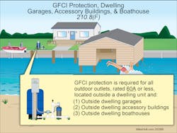
(1) Outside dwelling garages
(2) Outside dwelling accessory buildings
(3) Outside dwelling boathouses
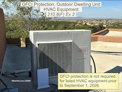
Exception No. 2: GFCI protection is not required for listed HVAC equipment prior to Sep. 1, 2026 (Fig. 8).
Author’s comment:
In accordance with UL 60335-2-40, listed HVAC equipment includes air-conditioning and heat pumps used for cooling and heating.
Change #10
NEW
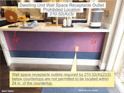
Section 210.52(A)(5) Wall Receptacle Outlets Below Countertop
Analysis of the change:
Receptacle outlets are now prohibited within 24 in. below the countertop surface. The 2023 Code addressed the Consumer Product Safety Commission reports on incidents caused by hanging cords off kitchen island and peninsula tops. However, it unintentionally allows other receptacles to be mounted on the sides of kitchen islands and peninsulas. Therefore, the rule was revised to prohibit “required and permitted” wall receptacle outlets installed below freestanding bar-type counters within 24 in. of the countertop surface.
New or revised Code language:
(5) Prohibited Receptacle Outlet Locations. Wall space receptacle outlets required by Sec. 210.52(A)(2)(3) installed below countertops are not permitted to be located within 24 in. of the countertop (Fig. 9).
Change #11
NEW
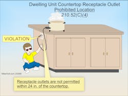
Section 210.52(C)(4) Receptacle Outlets Below Countertop
Analysis of the change:
Receptacle outlets are prohibited within 24 in. below the countertop surface. The 2023 Code changed countertop receptacle requirements to address the Consumer Protection Safety Commission reports of children suffering burn injuries from pulling appliance cords hanging off kitchen islands and peninsula countertops. These changes unintentionally allowed other permitted receptacles to be placed in these areas, creating the same hazard. The rule was revised this cycle to prohibit both “required and permitted” receptacle outlets from being located within 24 in. of the kitchen countertop surface.
New or revised Code language:
(4) Prohibited Receptacle Outlet Locations. Receptacle outlets are not permitted within 24 in. of the countertop (Fig. 10).
Change #12
RELOCATED
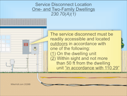
Section 230.70(A) Service Disconnect Location
Analysis of the change:
Service disconnects for one- and two-family dwellings must be located outdoors. The emergency disconnect rules in Sec. 230.85 were deleted. Now the service disconnects for one- and two-family dwellings must be outside, on, or within sight of the dwelling unit in accordance with Sec. 110.29.
New or revised Code language:
(A) Service Disconnect Location. Service equipment disconnects must be installed in accordance with the following:
(1) One- and Two-Family Dwellings. The service disconnect must be readily accessible and located outdoors in accordance with one of the following:
(1) On the dwelling unit.
(2) Within sight and not more than 50 ft from the dwelling unit in accordance with Sec. 110.29 (Fig. 11).
Change #13
EXPANDED
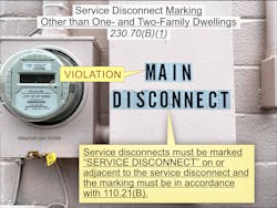
Section 230.70(B) Service Disconnect Markings
Analysis of the change:
The marking requirements of the service disconnect were significantly revised. These new marking rules make it clear exactly how to label and where the label is required for service disconnects.
New or revised Code language:
(B) Service Disconnect Marking. Service disconnects must be marked as follows:
(1) Marking, Other than One- and Two-Family Dwellings. Service disconnects must be marked “SERVICE DISCONNECT” on or adjacent to the service disconnect. The marking must be of sufficient durability to withstand the environment, cannot be handwritten, and must be permanently affixed to the equipment in accordance with Sec. 110.21(B), as shown in Fig. 12.
(2) Marking, One- and Two-Family Dwellings. Enclosures of disconnects for one- and two-family dwellings must be marked “EMERGENCY DISCONNECT.” The marking must be of sufficient durability to withstand the environment, cannot be handwritten, and must be permanently affixed to the equipment in accordance with Sec. 110.21(B), as shown in Fig. 13.
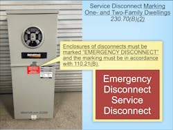
(1) Markings must be located on the outside front of the disconnect enclosure with a red background and white text
(2) Lettering must be at least ½ in. high
(D) Identification of Source Disconnects. Where the disconnecting means for energy source systems is not located adjacent to the service disconnect, a plaque or directory identifying the location of all energy source disconnecting means must be located adjacent to the service disconnect.
Note: For examples of energy source system disconnection means, see Secs. 445.18, 480.7, 705.20, and 706.15.
Change #14
CLARIFIED
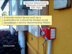
Section 230.70(F) Remote Control
Analysis of the change:
Remote disconnect control requirements were clarified by stating that in no case is a remote-control device permitted to be used as the service disconnect.
New or revised Code language:
(F) Remote Control. A remote-control device (such as a pushbutton for a shunt-trip breaker) is not considered a service disconnecting means (Fig. 14).
Change #15
NEW
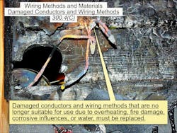
Section 300.4 Limitations
Analysis of the change:
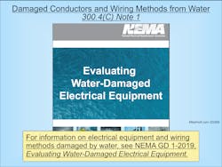
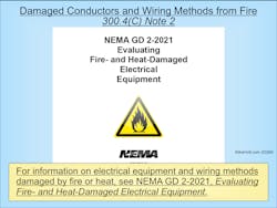
The NEC now addresses overheated, fire-damaged, or water-damaged wiring. A new rule states that overheated, fire- or water-damaged conductors, wiring methods, and equipment must be replaced. Two new Informational Notes refer to NEMA documents for evaluating fire- and water-damaged electrical equipment. This change removes any doubt that damaged wiring and equipment must be removed and replaced.
New or revised Code language:
(C) Damaged Conductors and Wiring Methods. Damaged conductors and wiring methods that are no longer suitable for use (due to overheating, fire damage, corrosive influences, or water) must be replaced (Fig. 15).
Note 1: For information on electrical equipment and wiring methods damaged by water, see NEMA GD 1-2019, Evaluating Water-Damaged Electrical Equipment (Fig. 16).
Note 2: For information on electrical equipment and wiring methods damaged by fire or heat, see NEMA GD 2-2021, Evaluating Fire- and Heat-Damaged Electrical Equipment (Fig. 17).
Change #16
NEW
Section 300.13 Securing and Supporting
Analysis of the change:
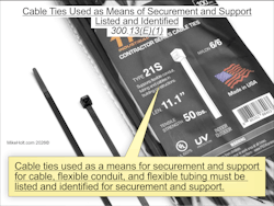
A new rule specifies that cable ties used for supporting and securing cables or flexible raceways must be listed and identified for that purpose. A new Informational Note provides guidance on which cable tie type is evaluated for securing and supporting.
New or revised Code language:
(E) Cable Ties Used as Means of Securement and Support.
(1) Cable Ties. Cable ties used as a means for securement and support for cable, flexible conduit, and flexible tubing must be listed and identified for securement and support (Fig. 18).
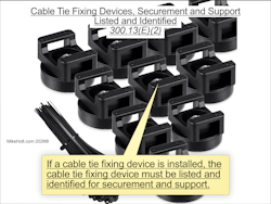
(2) Cable Tie Fixing Devices. If a cable tie fixing device is installed, the cable tie fixing device must be listed and identified for securement and support (Fig. 19).
Note: Type 2S and 21S cable ties are evaluated for securing and supporting cable, flexible conduit, and flexible tubing.
Change #17
NEW
Section 408.6 Short-Circuit Current Rating
Analysis of the change:
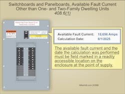
There are new requirements for marking, documenting, and recalculating available fault current at the line terminals of panelboards and switchboards for other than one- and two-family dwellings.
New or revised Code language:
Switchboards and panelboards must have a short-circuit current rating not less than the available fault current on the line side of the equipment. In other than one- and two-family dwelling units, switchboards and panelboards must comply with the following:
(1) Available fault current and the date the calculation was performed must be field marked in a readily accessible location on the enclosure at the point of supply (Fig. 20).
(2) Short-circuit current rating of switchboards and panelboards, at nominal circuit voltage (based on the overcurrent protective device), must be field marked in a readily accessible location on the enclosure
(3) Marking required by Sec. 408.6(1) and (2) must comply with Sec. 110.21(B)
(4) Available fault current calculation must be documented and made available to those authorized to inspect, install, or maintain the installation
(5) Where modifications occur that affect the available fault current at the line terminals of the equipment, the following applies:
a. Available fault current must be recalculated as necessary to ensure the equipment ratings are not less than the available fault current at the line terminals of the equipment
b. Required field markings in Sec. 408.6(1) must be adjusted to reflect the new level of available fault current
The interrupting rating of the replacement or added overcurrent protective devices must be equal to/greater than the available fault current marked on the equipment.
Note: For series combination systems, see Sec. 110.22.
Change #18
NEW
Section 555.9 Engineered Design
Analysis of the change:
A new rule permits the authority having jurisdiction (AHJ) to require an engineered electrical design for one- and two-family dwelling pier distribution systems in some cases. For larger systems or multi-slip marinas, be prepared to submit engineered plans. This change improves public safety on commercial docks by ensuring proper design and installation.
New or revised Code language:
Documentation of an engineered electrical design of the pier distribution system must be provided upon request of the authority having jurisdiction (AHJ).
Exception: An engineered design is not required for one- and two-family dwelling units if the system voltage is 240V, single-phase, or less.
Change #19
CLARIFIED
Section 555.13 Non-Current-Carrying Metal Parts Bonding
Analysis of the change:
Revisions clarify that only metal parts likely to become energized must be connected to the circuit equipment grounding conductor with a bonding conductor no larger than 8 AWG copper.
New or revised Code language:
All non-current-carrying metal parts that are likely to become energized must be connected to the branch circuit or feeder equipment grounding conductor by a bonding conductor not required to be larger than 8 AWG.
Change #20
EXPANDED
Section 555.35 GFPE and GFCI Protection
Analysis of the change:
The 2026 NEC expanded ground-fault protection of equipment (GFPE) protection on docks and piers. Revisions now require GFPE protection rated at 100mA or less for both branch circuits and feeders supplying docking facilities and piers. In short, all circuits supplying structures over water must be GFPE protected to reduce the risk of electric shock hazards in marine environments.
New or revised Code language:
(A) Feeders and Branch Circuits. Feeder and branch-circuit conductors on docking facilities and piers must be GFPE protected with a trip current not exceeding 100mA, as shown in Fig. 21.

Change #21
NEW
Section 555.35 GFPE Performance Testing
Analysis of the change:
A new requirement specifies that GFPE protection systems must be coordinated and performance tested by a qualified person. Proper coordination of GFPE devices helps prevent nuisance tripping, ensuring a safe and reliable electrical system in marina environments.
New or revised Code language:
(F) Coordination and Performance Testing. GFPE protection systems must be coordinated and performance tested by qualified persons in accordance with the manufacturerʼs instructions. A written record of this testing must be made available to the authority having jurisdiction (AHJ).
Change #22
NEW
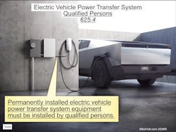
Section 625.4 Qualified Persons
Analysis of the change:
A new Section requires that permanently installed electric vehicle power transfer equipment (such as Level 2 or higher chargers) must be installed by a qualified person (as defined in Art. 100).
New or revised Code language:
Permanently installed electric vehicle power transfer system equipment must be installed by qualified persons (Fig. 22).
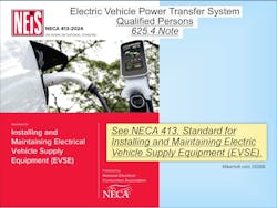
Note: See NECA 413, Standard for Installing and Maintaining Electric Vehicle Supply Equipment (EVSE) (Fig. 23).
Change #23
NEW
Section 625.5 Field Markings on EVSE Enclosures
Analysis of the change:
A new section requires permanent, visible markings on the outside of electric vehicle supply equipment (EVSE) enclosures. These markings show the voltage, number of phases, frequency, full-load current, and short-circuit current rating. Since EVSE installations allow field-adjustable current settings, these markings provide a quick way to verify proper circuit sizing and short-circuit rating before energizing the equipment.
New or revised Code language:
Electric vehicle supply equipment must have permanent field markings on the outside of the equipment enclosure that are visible after the installation, containing the following:
(1) Supply voltage, number of phases, frequency, and full-load current for each incoming supply circuit
(2) Short-circuit current rating of the electric vehicle supply equipment based on one of the following:
a. Short-circuit current rating of a listed and labeled assembly
b. Short-circuit current rating established utilizing an approved method
Note: For an example of an approved method, see UL 2594, Standard Electric Vehicle Supply Equipment.
Author’s comment:
EVSE equipment can have the full load current adjusted in accordance with Sec. 625.42(B); therefore, this field marking is necessary to verify proper circuit sizing.
Change #24
NEW
Section 625.43 Disconnecting Means
Analysis of the change:
New emergency shutoff requirement for permanently connected EVSEs was added for first responders. For other than one- and two-family dwellings, permanently connected EVSEs must have an emergency shutoff device installed within sight — and located no closer than 20 ft and no farther than 100 ft — from the equipment. This provides a safe distance in the event of an electric vehicle fire. The emergency shutoff device must be clearly marked to warn that the vehicle will remain energized — even after the EVSE is de-energized. With charging stations becoming more common, this rule ensures first responders and personnel have a quick, safe way to disconnect power in an emergency.
New or revised Code language:
(D) Emergency Shutoff.
(1) Emergency Disconnect. For other than one- and two-family dwellings, the emergency shutoff disconnect for EVSE and WPTE must:
(1) Be installed at a readily accessible location not less than 20 ft, or more than 100 ft, and within sight of equipment
(2) Be located within sight of the emergency shutoff
(3) Be marked “EVSE EMERGENCY DISCONNECT” and “WARNING: ELECTRIC VEHICLES WILL REMAIN ENERGIZED” in accordance with Sec. 110.22(A)
(4) Be a manual reset type
(5) Disconnect all phase conductors of the circuits simultaneously from the source of supply
(2) Equipment Disconnect Serving as Emergency Shutoff Disconnect. The equipment disconnect [Sec. 625.43(C)] is permitted to serve as the emergency shutoff disconnect — if the equipment disconnect complies with Sec. 625.43(D) requirements.
Change #25
NEW
Section 625.44 Equipment Connections
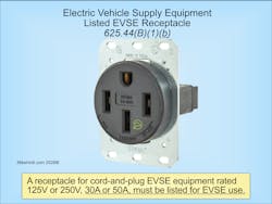
Analysis of the change:
A new rules addresses when receptacles for EVSE must be listed for EVSE use. The most common point of failure in an electrical system is at the connection point. All 30A, 50A, and 60A receptacles used for EV charging must be listed for EVSE use. This change addresses the growing issue of receptacle failures due to high temperatures under continuous loads — especially with cord and plug connections. Receptacles listed for EVSE use are specifically designed and tested for continuous load conditions, helping ensure safe and reliable charging over extended periods.
New or revised Code language:
(B) Hand-Fastened Equipment. Equipment that is hand-fastened must be connected to the premises wiring system by one of the following methods:
(1) Nonlocking, 2-pole, 3-wire grounding-type receptacle outlet rated 125V or 250V, single-phase, in accordance with one of the following:
a. 15A or 20A
b. 30A or 50A listed for EVSE and WPTE use (Fig. 24)
(2) Nonlocking, 3-pole, 4-wire grounding-type receptacle outlet rated 250V, 3-phase, in accordance with one of the following:
a. 15A or 20A
b. 30A, 50A, or 60A listed for EVSE and WPTE use
(3) Nonlocking, 3-pole, 4-wire grounding-type receptacle outlet rated 125V/250V, single-phase, in accordance with one of the following:
a. 15A or 20A
b. 30A, 50A, or 60A listed for EVSE and WPTE use
Author’s comment:
There are concerns in the industry about the failure of the standard-grade (residential) receptacle used for the connection of EV equipment. Consideration should be given to the use of receptacles that are specifically designed for EV equipment use.
New, Relocated, or Renamed Articles
• Article 120. Branch-Circuit, Feeder, and Service Load Calculations. Relocated from Art. 220, Art. 120 contains the requirements necessary for calculating demand loads for branch circuits, feeders, and services. This change was made because load calculations apply generally to all installations.
• Article 130. Energy Management Systems. As part of the larger reorganization of the NEC, requirements for energy management systems (previously contained in Art. 750) were relocated to Art. 130. Part I applies to both energy management systems (EMSs) and power control systems (PCSs), which are EMS that also provide overload protection. Part II applies only to power control systems.
• Article 206. Non-Power-Limited Remote-Control and Signaling Circuits. This Article provides the general requirements for non-power-limited remote-control and signaling circuits.
• Article 406. The scope of Art. 406 was revised to cover “wiring devices” instead of just receptacles. Under the new Art. 100 definition, wiring devices now include receptacles, cord connectors, attachment plugs, snap switches, dimmers, and electronic control switches. The major shift was relocating small switch-type wiring devices from Art. 404 into Art. 406. This reorganization groups devices with similar construction and performance requirements under one article, improving the clarity and usability of the Code. This Article contains the requirements for the rating, type, and installation of wiring devices.
• Article 624. Electric Self-Propelled Vehicle Power Transfer Systems (ESVSEs). This Article covers the electrical conductors and equipment connecting an electric self-propelled vehicle (ESV) to premises wiring for the purposes of charging, power export, or bidirectional current flow. It applies to vehicles not defined as electric vehicles in Art. 100, such as forklifts, airport ground equipment, construction machinery, golf carts, lawnmowers, and electric boats.
• Article 772. Fire Resistive Cable Systems. This Article was previously located in Art. 728.
Limited-Energy Systems Articles
Many of the Articles in Chapters 7 and 8, which deal with limited-energy systems, have been consolidated into fewer Articles for better organization and consistency.
• Article 720. General Requirements for Limited-Energy Systems Wiring Methods and Materials. This new Article covers the general wiring methods and materials requirements for limited-energy system installations. It was created to consolidate the general rules for limited-energy systems, including Class 2, Class 4, power-limited fire alarm (PLFA), and communication systems. If you’re installing low-voltage wiring, be sure to review Art. 720 before roughing in cables to ensure a Code-compliant installation.
• Article 721. Power Sources for Limited-Energy Systems. This Article covers power source requirements for limited-energy system circuits.
• Article 722. Limited-Energy Cables for Power-Limited Circuits, Fault-Managed-Power Circuits, Optical Fiber Circuits, and Communications Circuits. This Article contains the general requirements for limited-energy cables.
• Article 723. Raceways, Cable Routing Assemblies, and Cable Trays for Limited-Energy Systems. This Article covers the application and installation of raceways, cable routing assemblies, and cable trays for limited-energy systems.
• Article 742. Overvoltage Protection of Limited-Energy Systems. This Article covers the overvoltage protection requirements for limited energy systems installations.
• Article 750. Grounding and Bonding of Limited-Energy Systems. This Article covers the grounding and bonding requirements for limited-energy systems.
New Articles Over 1,000VAC or 1,500VDC
• Article 245. Overcurrent Protection for Systems. This Article covers overcurrent protection requirements for nominal voltage systems rated over 1,000VAC or 1,500VDC.
• Article 265. Branch Circuits Over 1,000V [From Part II of deleted Art. 235]. This Article provides the general requirements for branch circuits of nominal voltage systems rated over 1,000VAC or 1,500VDC.
• Article 266. Feeders Over 1,000VAC, 1,500VDC Nominal. This Article covers the installation requirements, overcurrent protection requirements, minimum size, and ampacity of conductors for feeders of nominal voltage systems rated over 1,000VAC or 1,500VDC.
• Article 267. Outside BC and Feeders Over 1,000VAC, 1,500VDC Nominal. This Article covers requirements for outside branch circuits and feeders of nominal voltage systems rated over 1,000VAC or 1,500VDC.
• Article 268. Services Over 1,000VAC, 1,500VDC, Nominal. This Article covers installation requirements for service conductors and equipment for control and protection of services for nominal voltage systems rated over 1,000VAC or 1,500VDC. In no case can this Article apply to equipment on the supply side of the service point.
• Article 270. Grounding and Bonding of Systems Over 1,000VAC, 1,500VDC, Nominal. This Article covers general requirements for grounding and bonding of electrical installations for nominal voltage systems rated over 1,000VAC or 1,500VDC.
• Article 305. General Requirements for Wiring Methods and Materials. This Article covers wiring methods and materials for nominal voltage systems rated over 1,000VAC or 1,500VDC.
• Article 315. Medium Voltage Conductors, Cable, Cable Joints, and Cable Terminations. This Article covers the use, installation, construction specifications, and ampacities for Type MV medium-voltage conductors, cable, cable joints, and cable terminations. This Article includes nominal voltage systems from 2,001VAC to 35,000VAC and 2,001VDC to 2,500VDC.
• Article 495. Equipment Over 1,000VAC, 1,500VDC, Nominal. This Article covers the general requirements for equipment operating at nominal voltage systems more than 1,000VAC or 1,500VDC.
Deleted Articles
About the Author

Mike Holt
Mike Holt is the owner of Mike Holt Enterprises (www.MikeHolt.com), one of the largest electrical publishers in the United States. He earned a master's degree in the Business Administration Program (MBA) from the University of Miami. He earned his reputation as a National Electrical Code (NEC) expert by working his way up through the electrical trade. Formally a construction editor for two different trade publications, Mike started his career as an apprentice electrician and eventually became a master electrician, an electrical inspector, a contractor, and an educator. Mike has taught more than 1,000 classes on 30 different electrical-related subjects — ranging from alarm installations to exam preparation and voltage drop calculations. He continues to produce seminars, videos, books, and online training for the trade as well as contribute monthly Code content to EC&M magazine.