Practically Speaking: Choose Your Colors Wisely
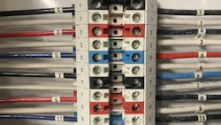
Does either one of the installations below comply with the requirements in Sec. 210.5(C)(1)
for identification of the ungrounded branch-circuit conductors if the premises has more than one nominal voltage system?
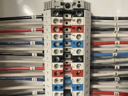
I get some fascinating responses when I ask this question during my classes and seminars. Many people feel that Photo 1 definitely does not comply, as the black, red, and blue colors are inconsistently mixed and matched together. Many people believe that Photo 2 complies with a typical wiring scheme for 3-way switches wired using MC cable. In fact, Photo 1 may be a Code-compliant installation while Photo 2 may be a violation.
Let me break down Photo 1. Using black, red, and blue insulation to identify the ungrounded conductors of 120V/208V, 3-phase systems is a widespread practice. Using numbers to identify which circuit each conductor is connected to is also very common.
In this particular installation, the black, red, and blue insulation is used only to identify the nominal system voltage, but not to indicate which phase each conductor is connected to.
The numbers are always used to indicate which phase. In other words, black, red, and blue always indicate 120V/208V systems, but phase “A” could be black, red, or blue. However, phase “A” will always be numbers 1, 7, 13, 19, or 25. This combination of black, red, and blue colors plus numbers is used to identify each ungrounded conductor by phase or line and by nominal voltage system. While perhaps less common than other methods, this method could be Code-compliant.
Photo 2 is a little simpler to break down. In this building, brown, orange, and yellow insulation was the only method used to identify the ungrounded conductors for 277V/480V, 3-phase systems. There were no numbers, letters, or other identifiers used. However, brown insulation was specifically reserved for phase “A”, orange for phase “B,” and yellow for phase “C.”
To which phase is this 3-way switch connected? Your guess is as good as mine. Perhaps if the brown, orange, and yellow had additional markings such as “Line 1,” or “Phase A,” it could provide an installation that complies with Sec. 210.5(C)(1). Presently, however, I would say this installation is a failure, as there is no identification for which phase is supplying power here. Using only colored insulation as a means for complying with Sec. 210.5(C)(1) may be a little trickier than it seems. I suppose the same could also be said for Sec. 215.12(C)(1) when it comes to identifying feeder conductors.
About the Author

Russ LeBlanc
Owner
Russ started in the electrical trade as an apprentice in 1985. He worked his way up to become a Journeyman Electrician and then eventually became a Master Electrician and Licensed Construction Supervisor. In 1999 Russ become an Electrical Instructor for The Peterson School of Engineering in Massachusetts where he developed his passion for teaching, and quickly became Department Head of Electrical Instruction. Russ has taught thousands of apprentices, electricians, engineers, inspectors, and other electrical professionals during his career as an instructor. He continues to provide electrical professionals with Electrical Code seminars, Arc-Flash Awareness training seminars and educational material through his LeBlanc Consulting Services in North Reading, MA whose specialty is educating electricians. He has been an active member of the NFPA Electrical Section and has authored hundreds of National Electrical Code proposals and comments which have become Code rules to improve the safety for the electrical industry. Russ is also an IAEI certified Electrical Inspector.
Please visit www.russleblanc.net for more information.