NEC Requirements for Sizing Outlet Boxes
The consequences of undersizing outlet boxes can include damaged wiring, overheating, and even electrical fires. But you can’t just oversize boxes “to be on the safe side” because that wastes space and money. A 10 × 10 × 4 box for three 12 AWG conductors would prevent an undersizing problem, but it would also be ridiculously big. So how small is too small, and what size is adequate?
An outlet box is generally used for the attachment of devices and luminaires and has a specific amount of space (volume) for conductors, devices, and fittings. The volume taken up by conductors, devices, and fittings in a box must not exceed the box fill capacity.
The requirements for sizing boxes and conduit bodies containing conductors 4 AWG and larger are found in Sec. 314.28. The requirements for sizing handhole enclosures are in Sec. 314.30(A).
Boxes containing 6 AWG and smaller conductors must be sized in an approved manner to provide free space for all conductors, devices, and fittings. In no case can the volume of the box, as calculated in Sec. 314.16(A), be less than the volume requirement as calculated in Sec. 314.16(B).
Same Size Conductors
When all the conductors in an outlet box are the same size (insulation doesn’t matter), you can use Table 314.16(A) to determine the:
(1) Number of conductors permitted in the outlet box, or
(2) Outlet box size required for the given number of conductors.
Consider this sample problem: What size 4 in. square outlet box will be required for three 12 AWG THW and six 12 AWG THHN conductors? A quick check of Table 314.16(A) reveals that a 4 in. × 1½ in. square box permits nine 12 AWG conductors; the insulation type isn’t a factor when calculating box fill.
If the outlet box contains switches, receptacles, luminaire studs, luminaire hickeys, cable clamps, or equipment grounding conductors (EGCs), then you must make an allowance for these items per Sec. 314.16(B)(1) through (5). These items aren’t reflected in Table 314.16(A).
Box Volume
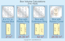
The volume of a box is the total volume of its assembled parts, including plaster rings, raised covers, and extension rings. The total volume includes only those parts that are marked with their volumes in cubic inches [Sec. 314.16(A)] or included in Table 314.16(A) (Fig. 1).
Consider this sample problem. What’s the total volume of a 4 × 4 × 1½ outlet box, with a 4 × 4 × 1½ extension ring, and a cover having a volume of 7.50 cu. in.? (Fig. 2)
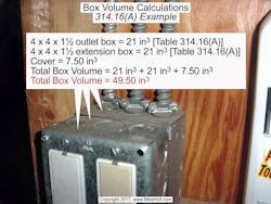
Volume of outlet box = 21 cu. in.
Volume of extension ring = 21 cu. in.
Volume of cover = 7.50 cu. in.
Therefore, the total volume of assembled parts = 21 + 21 + 7.50 = 49.50 cu. in.
Box with Barriers
Where a box is provided with barriers, the volume is apportioned to each of the resulting spaces. Each barrier — if not marked with its volume — is considered to take up ½ cu. in. if metal and 1 cu. in. if nonmetallic [Sec. 314.16(A)].
Box Fill
Many items that might go in a box are not counted in the fill calculations. Table 314.16(A) doesn’t consider switches, receptacles, luminaire studs, luminaire hickeys, cable clamps, or EGCs.
Raceway and cable fittings, including locknuts and bushings, aren’t counted for box fill calculations. Conductors that originate and terminate within the box, such as pigtails, aren’t counted at all.
EGCs and up to four 16 AWG and smaller fixture wires can be omitted from box fill calculations if they enter the box from a domed luminaire or similar canopy, such as a ceiling paddle fan canopy [Sec. 314.16(B)(1) Exception].
The calculated conductor volumes determined by Sec. 314.16(B)(1) through (B)(5) are added to determine the total volume of the conductors, devices, and fittings:
(1) Conductors. Each unbroken conductor that runs through a box and each conductor that terminates in a box counts as a single conductor volume per Table 314.16(B). Each loop or coil of
unbroken conductor having a length of at least twice the minimum length required (12 in.) for free conductors in Sec. 300.14 counts as two conductor volumes.
(2) Cable clamps. One or more internal cable clamps count as a single conductor volume per Table 314.16(B), based on the largest conductor that enters the box. Cable connectors that have their clamping mechanism outside the box are not counted.
(3) Support fittings. Each luminaire stud or luminaire hickey counts as a single conductor volume per Table 314.16(B), based on the largest conductor that enters the box.
(4) Device yokes. Each single-gang device yoke (regardless of the physical size of the device) counts as two conductor volumes based on the largest conductor that terminates on the device per Table 314.16(B). Each multigang device yoke counts as two conductor volumes for each gang, based on the largest conductor that terminates on the device per Table 314.16(B).
(5) EGC. All EGCs in a box count as a single conductor volume per Table 314.16(B), based on the largest EGC entering the box. Insulated EGCs for receptacles having insulated grounding terminals (isolated ground receptacles) [Sec. 250.146(D)] count as a single conductor volume per Table 314.16(B).
Outlet Box Sizing Steps
To determine the size of the outlet box when the conductors are of different sizes (insulation isn’t a factor), follow these steps:
Step 1: Determine the number and size of conductor equivalents in the box.
Step 2: Determine the volume of the conductor equivalents from Table 314.16(B).
Step 3: Size the box by using Table 314.16(A).
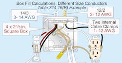
Let’s work an example problem: What’s the minimum depth 4-in. square outlet box required for one 14/3 with ground Type NM cable that terminates on a 3-way switch, and one 12/2 w/G Type NM cable that terminates on a receptacle? The box has internally installed cable clamps (Fig. 3).
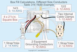
Step 1: Determine the number of each size conductor.
14/3 NM = three 14 AWG conductors
Switch total = five 14 AWG conductors
12/2 NM = two 12 AWG conductors
Cable clamp = one 12 AWG conductor
Receptacle = two 12 AWG conductors
EGC = one 12 AWG conductor
Total = six 12 AWG conductors
All EGCs count as one conductor, based on the largest EGC entering the box [Sec. 314.16(B)(5)].
Step 2: Determine the volume of the conductors [Table 314.16(B)].
14 AWG, 2 cu. in. each
2 cu. in. × five conductors = 10.00 cu. in.
12 AWG, 2.25 cu. in. each
2.25 cu. in. × six conductors = 13.50 cu. in.
Total volume= 10.00 cu. in. + 13.50 cu. in. = 23.50 cu. in.
Step 3: Select the outlet box from Table 314.16(A).
A 4-in. × 21/8-in. square, 30.30 cu. in. box meets the minimum cu. in. requirements.
Try this twist on a box sizing problem: How many 14 AWG conductors can be added to a 4-in. × 21/8-in. square box that has a plaster ring of 3.60 cu. in. if the box already contains two receptacles, five 12 AWG conductors, and one 12 AWG EGC?
Step 1: Determine the number and size of the existing conductors.
Two receptacles (two yokes × two conductors) = four 12 AWG conductors. Add that to the five 12 AWG conductors and one 12 AWG EGC to get a total of 10 12 AWG conductors.
Step 2: Determine the volume of the existing conductors [Table 314.16(B)].
12 AWG conductor = 2.25 cu. in.
Total conductor volume = 10 wires × 2.25 cu. in. = 22.50 cu. in.
Step 3: Determine the space remaining for the additional 14 AWG conductors.
As per Table 314.16(A), the space for the box = 30.30 cu. in. and the space for the extension ring = 3.60 cu. in.
Total space = 30.30 cu. in. + 3.60 cu. in. = 33.90 cu. in.
Therefore, the remaining available space = 33.90 cu. in. – 22.50 cu. in. = 11.40 cu. in.
Step 4: Determine the number of 14 AWG conductors permitted in the spare space.
Conductors added = 11.40 cu. in. ÷ 2 cu. in. = 5.70
Conductors added = five conductors (Rounding up doesn’t apply to box fill.)
Two Methods
If conductors are the same size, then add them together and size the box using the AWG size columns of Table 314.16(A). However, if the box contains different sizes of conductors, then use Table 314.16(B) to find the area of each conductor, add them up, and size the box from Table 314.16(A) using the cu. in. column.
To get good at using these methods, you should try to practice often. For example, you can size boxes on the job site to double-check the drawings — or set aside some time to draw out 10 picture problems, and then solve two each day until you have solved them all.
These materials are provided to us by Mike Holt Enterprises of Leesburg, Fla. To view additional Code training materials offered by this company, visit www.mikeholt.com.
About the Author

Mike Holt
Mike Holt is the owner of Mike Holt Enterprises (www.MikeHolt.com), one of the largest electrical publishers in the United States. He earned a master's degree in the Business Administration Program (MBA) from the University of Miami. He earned his reputation as a National Electrical Code (NEC) expert by working his way up through the electrical trade. Formally a construction editor for two different trade publications, Mike started his career as an apprentice electrician and eventually became a master electrician, an electrical inspector, a contractor, and an educator. Mike has taught more than 1,000 classes on 30 different electrical-related subjects — ranging from alarm installations to exam preparation and voltage drop calculations. He continues to produce seminars, videos, books, and online training for the trade as well as contribute monthly Code content to EC&M magazine.