Courtesy of www.MikeHolt.com. Based on the 2020 NEC.
Class 2 circuits are limited to voltage and current values that don’t (usually) present a shock or fire hazard.
The power supply for a Class 2 circuit must be as follows [725.121(A)]:
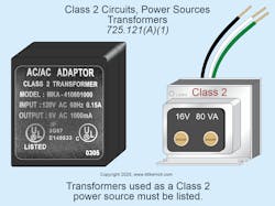
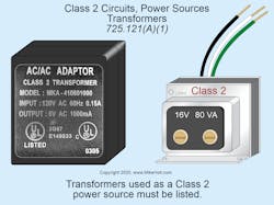
(1) A listed Class 2 transformer (Fig. 1).
(2) A listed Class 2 power supply.
(3) Equipment listed as a Class 2 power source.
Exception No. 2: Where a circuit has an energy level at or below the limits in Chapter 9, Table 11(A) and 11(B), the equipment need not be listed as Class 2.
(4) Listed audio/video information technology equipment, communications, and industrial equipment limited-power circuits.
A fifth power supply available to Class 2 circuits is a battery source/system that is listed and identified as Class 2.
Class 2 cables
For corrosive, damp, or wet locations, Class 2 cables must be identified for the location per Sec. 110.11 and Sec. 310.10(F). Conductors and cables in underground raceways [Sec. 300.5(B)] or in raceways above ground in wet locations [Sec. 300.9] must also be identified for wet locations. Where corrosion may occur, follow the requirements of Sec. 300.6 [Sec. 725.3(L)].
Class 2 cables can be installed in:
- Cable routing assemblies selected per Table 800.154(c), listed per Sec. 800.182, and installed per Sec. 800.110(C) and Sec. 800.113 [Sec. 725.3(M)].
- Communications raceways selected per Table 800.154(b), listed per Sec. 800.182, and installed per Sec. 800.113 and Sec. 362.24 through Sec. 362.56, where the requirements applicable to electrical nonmetallic tubing apply [Sec. 725.3(N)].
The requirements of Sec. 310.14(A)(3) for the temperature limitation of conductors apply to Class 2 cables [Sec. 725.3(O)]. The accessible portion of Class 2 cables not terminated at equipment or tagged for future use must be removed [Sec. 725.25].
Marking
The power sources for power-limited circuits in Sec. 725.121(A)(3) and power-limited circuits for listed audio/video equipment, listed information technology equipment, listed communications equipment, and listed industrial equipment in Sec. 725.121(A)(4) must be labeled with the maximum voltage and rated current output per conductor for each connection point on the power source [Sec. 725.121(C)].
Equipment supplying Class 2 circuits must be durably marked to indicate each circuit that is Class 2 [Sec. 725.124].
Wiring methods
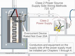
Conductors and equipment on the supply side of the Class 2 power supply must be installed per Chapters 1 through 4. The overcurrent protection for Class 2 transformers or power supplies must not exceed 20A [Sec. 725.127] (Fig. 2).
Class 2 circuits can use a Class 1 wiring method per Sec. 725.46 [Sec. 725.130(A)]. Class 2 circuits can be reclassified as Class 1 circuits if the Class 2 equipment markings are eliminated, and the circuit is installed using a Chapter 3 wiring method per Sec. 725.46 [Sec. 725.130(A), Exception No. 2].
Where a Class 2 circuit is reclassified as a Class 1 circuit, it can be run in the same raceway, cable, or enclosure with power conductors of functionally associated equipment [Sec. 725.48(B)]. Class 2 circuits reclassified and installed as Class 1 circuits are no longer Class 2 circuits, regardless of their continued connection to a Class 2 power source [Sec. 725.130(A) Note].
Class 2 circuits can use Class 2 wiring of the type in Sec. 725.179 if installed per Sec. 725.133 and Sec. 725.154 [Sec. 725.130(B)].
Cable installation
Class 2 cable installation must comply with Sec. 725.135(A) through (M). For example:
- Plenum-rated Class 2 cables can be installed within plenum air spaces per Sec. 725.3(C) Exception No. 2 if the Class 2 cables are plenum rated except were installed in a metallic raceway per Sec. 300.22(C) [Sec. 725.135(C)].
- Cables installed in cable trays outdoors must be Type PLTC.
You’ll see some overlap, also. For example, the following cables are permitted in cable trays inside buildings Sec. 725.135(H) and in dwelling units [Sec. 725.135(M)]: PLTC cables and types CL2P, CL3P, CL2R, CL3R, CL2, and CL3.
Separation
Class 2 cables are not permitted in any enclosure or raceway with power and Class 1 circuits, except as permitted in Sec. 725.136(B) through (I).
For example, Class 2 circuit conductors can be installed with power conductors and Class 1 conductors if separated by a barrier [Sec. 725.136(B)].
You can mix conductors of different circuits, per Sec. 725.139(A) through (F). For example, Class 2 circuit conductors can be in the same:
- Cable, cable routing assembly, enclosure, or raceway with other Class 2 circuit conductors [Sec. 725.139(A)].
- Cable with conductors of communications circuits if the cable is a listed communications cable that has been installed per Part V of Art. 805 [Sec. 725.139(D)].
Power and data transmission
Section 300.11 and Parts I and III of Art. 725 apply to Class 2 circuits that transmit power and data. Conductors that carry power and data must be copper, and the current cannot exceed the current limitation of the connectors [Sec. 725.144]. Six informational notes follow Sec. 725.144 (and these have been heavily revised with the 2020 cycle). For example:
- Note 1: Closed-circuit TV camera (CCTV) circuits are an example of cables that transmit power and data.
- Note 6: The rated current for power sources covered in Sec. 725.144 is the output current per conductor the power source is designed to deliver to an operational load at normal operating conditions, as declared by the manufacturer. In the design of these systems, the actual current in a given conductor might vary from the rated current per conductor by as much as 20%. An increase in current in one conductor is offset by a corresponding decrease in current in one or more conductors of the same cable.
Table 725.144 is an ampacity table for 4-pair Class 2 power/data cables. Make sure you understand the notes that come with it. For example, where only half of the conductors in each cable are carrying current, you can increase the values in the table by a factor of 1.40 [Table 725.144 Note 2].
Compliance with Table 725.144 is not required for conductors 24 AWG or larger where the rated current per conductor of the power source does not exceed 0.30A.
One example of the use of Class 2 cables is a network of closed-circuit TV cameras using 24 AWG, 60°C-rated, Type CL2R, Cat. 5e balanced twisted-pair cabling.
Cable Types CL3P-LP, CL2P-LP, CL3R-LP, CL2R-LP, CL3-LP, or CL2-LP can supply power to equipment from a power source with a rated current per conductor up to the marked current limit located immediately following the suffix “-LP” and can transmit data to the equipment [Sec. 725.144(B)].
Where the number of bundled LP cables is 192 or less, and the selected ampacity of the cables per Table 725.144 exceeds the marked current limit of the cable, you can determine the ampacity from the table. For ambient temperatures above 30°C, you must apply the correction factors of Table 310.15(B)(1) or Equation 310.15(B)(2).
The Class 2-LP cables must comply with the following, as applicable:
(1) Cables with the suffix “-LP” can be installed in bundles, raceways, cable trays, communications raceways, and cable routing assemblies.
(2) Cables with the suffix “-LP” and a marked current limit must follow the substitution hierarchy of Table 725.154 and Figure 725.154(A) in the NEC for the cable type without the suffix “-LP” and without the marked current limit.
(3) System design is permitted by qualified persons under engineering supervision.
An example of a limited power (LP) cable is a cable marked Type CL2-LP (0.5A), 23 AWG.
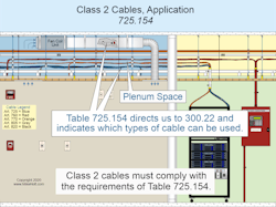
Class 2 cables must comply with Sec. 725.154(A) through (C) and Table 725.154 (Fig. 3).
For example, cable substitutions can be made per Table 725.154(A) and Figure 725.154(A) Cable Substitution Hierarchy.
There is no Table 725.154(B), but preceding Table 725.154(A) — as you move through Art. 725 from front to back — is Table 725.154. This table shows you which of the 10 cable types you can use for a given application. For example, in a riser vertical run you can use CL2P, CL3P, CL2R, and CL3R, but not CL2, CL3, CL2X, CL3X, CMUC, or PLTC.
Avoiding Class 2 errors
The supply-side equipment and wiring of Class 2 circuits fall under Chapters 1 through 4, not under Art. 725. On the load side, you need to follow Art. 725 requirements. Remember that Class 2 circuits are limited to prevent shock or fire. That means you separate them from circuits that are not so limited. You also must use the cable type that is appropriate for the application.
If you have Class 1, Class 2, and Class 3 remote control and signaling circuits in the same facility, mark these at each panel and junction box (both on the drawings and physically), so they don’t get mixed together.
These materials are provided by Mike Holt Enterprises in Leesburg, Fla. To view Code training materials offered by this company, visit www.mikeholt.com/code.
About the Author

Mike Holt
Mike Holt is the owner of Mike Holt Enterprises (www.MikeHolt.com), one of the largest electrical publishers in the United States. He earned a master's degree in the Business Administration Program (MBA) from the University of Miami. He earned his reputation as a National Electrical Code (NEC) expert by working his way up through the electrical trade. Formally a construction editor for two different trade publications, Mike started his career as an apprentice electrician and eventually became a master electrician, an electrical inspector, a contractor, and an educator. Mike has taught more than 1,000 classes on 30 different electrical-related subjects — ranging from alarm installations to exam preparation and voltage drop calculations. He continues to produce seminars, videos, books, and online training for the trade as well as contribute monthly Code content to EC&M magazine.


